


80127801
Installation Manual
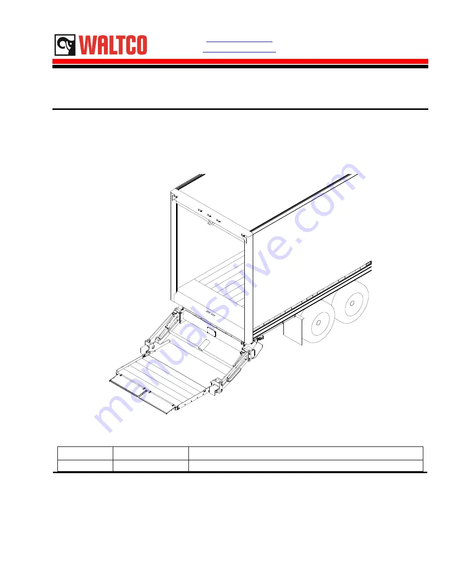
GT-33, 44, 55
3300, 4400, 5500 lb. Capacity Flipaway Liftgates
Last Change:
Date
Pages
Description
01-2022
ALL
Updated mounting requirements and line drawings
Waltco Lift Corp.
Corporate Office United States
1777 Miller Pkwy
Streetsboro, OH 44241
P: 330.633.9191
F: 330.633.1418
EO:10
848
Rev 03
01-2022
www.waltco.com
Phone:
800.411.5685
Fax:
800.411.5684
Summary of Contents for GT-33
Page 9: ...Chapter 3 Basic Mounting Requirements GR10132 9 ...
Page 21: ...Chapter 4 Liftgate Installation Hydraulic Schematic Single Pump Gravity Down 21 ...
Page 22: ...Chapter 4 Liftgate Installation Hydraulic Schematic Single Pump Power Down 22 ...
Page 23: ...Chapter 4 Liftgate Installation Hydraulic Schematic Dual Pump Gravity Down 23 ...
Page 24: ...Chapter 4 Liftgate Installation Hydraulic Schematic Dual Pump Power Down 24 ...


