


EO:10338 Rev 02
03/2018
80117222
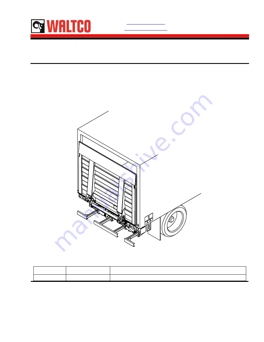
Owner’s Manual
BZ-33, BZ-44 Gen 7
3300 lb. & 4400 lb. Capacity Cantilever Liftgates
GR02912
Last Change
Date
Pages
Description
03/20/2018
23-25
REVISED ELECTRICAL SCHEMATICS
Waltco Lift Corp.
Waltco Lift Corp.
Waltco Lift Inc.
Corporate Office United State
United States
Canada
285 Northeast Ave.
620 S Hambledon Ave.
90 North Queen St.
Tallmadge, OH 44278
City of Industry, CA 91744
Etobicoke, ON M8Z 2C5
P: 330.633.9191
P: 626.964.0990
P: 888.343.4550
F: 330.633.1418
F: 626.964.0149
www.waltco.com
Phone:
800.211.3074
Fax:
800.211.3075


