background image

The TAD1242GE is a powerful, reliable 

and economical Generating Set Diesel 

Engine built on the dependable in-line six 

design.

Durability & low noise

Designed for easiest, fastest and most 

economical installation. Well-balanced to 

produce smooth and vibration-free opera-

tion with low noise level.

 To maintain a controlled working tem-

perature in cylinders and combustion 

chambers, the engine is equipped with 

piston cooling. The engine is also fitted 

with replaceable cylinder liners and valve 

seats/guides to ensure maximum durabil-

ity and service life of the engine.

Low exhaust emission

The state of the art, high-tech injection 

and charging system with low internal 

losses contributes to excellent combus-

tion and low fuel consumption.

 The TAD1242GE complies with EU 

Stage 2 and TA-Luft -50% exhaust emis-

sion regulations.

Easy service & maintenance

Easily accessible service and mainte-

nance points contribute to the ease of 

service of the engine.

Technical description:

Engine and block

– Optimized cast iron cylinder block with opti-

mum distribution of forces without the block

being unnessarily heavy.

– Wet, replaceable cylinder liners

– Piston cooling for low piston temperature

and reduced ring temperature

– Tapered connecting rods for reduce risk of

piston cracking

– Crankshaft induction hardened bearing

surfaces and fillets with seven bearings for

moderate load on main and high-end bear-

ings

– Case hardened and Nitrocarburized trans-

mission gears for heavy duty operation

– Keystone top compression rings for long

service life

– Viscous type crankshaft vibration dampers to

withstand single bearing alternator torsional

vibrations

– Replaceable valve guides and valve seats

– Over head camshaft and four valves per cyl-

inder

Lubrication system

– Full flow oil cooler

– Full flow disposable spin-on oil filter, for ex-

tra high filtration

– The lubricating oil level can be measured

during operation

– Gear type lubricating oil pump, gear driven

by the transmission

Fuel system

– Non-return fuel valve

– Electronic Unit Injectors

– Fuel prefilter with water separator and water-

in-fuel indicator / alarm

– Gear driven low-pressure fuel pump

– Fine fuel filter with manual feed pump and

fuel pressure switch

– Fuel shut-off valve, electrically operated

Cooling system

– Efficient cooling with accurate coolant con-

trol through a water distribution duct in the

cylinder block. Reliable sleeve thermostat

with minimum pressure drop

– Gear driven, maintenance-free coolant pump

with high degree of efficiency

– Coolant filter as standard

Turbo charger

– Efficient and reliable turbo charger

– Extra oil filter for the turbo charger

Electrical system

– Electronical Diesel Control III (EDCIII), an

electronically controlled processing system

which optimizes engine performance. It also

includes advanced facilities for diagnostics

and fault tracing

– Three different ways for the customer to

connect his controls and instrument to the

engine. CAN SAE J1939 interface, CIU

(Control interface unit) and Stand alone

connections.

– Sensors for oil pressure, oil temp, boost

pressure, boost temp, coolant temp, fuel

temp,  water in fuel, fuel pressure and two

speed sensors.

Features

– Maintained performance, air temp 40°C

– Cooling system (55°C)

– Fully electronic with Volvo Penta EDC III

– Dual frequency switch (between 1500 rpm and 1800 rpm)

– High power density

– Emission compliant

– Low noise levels

– Gen Pac configuration

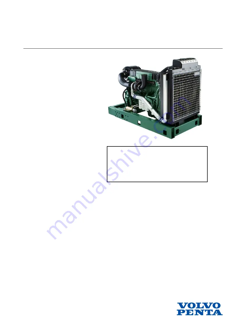
VOLVO PENTA GENSET ENGINE

TAD1242GE

1500 rpm, 387 kW (526 hp)  – 1800 rpm, 430 kW (585 hp)

Summary of Contents for TAD1242GE

Page 1: ...al vibrations Replaceable valve guides and valve seats Over head camshaft and four valves per cyl inder Lubrication system Full flow oil cooler Full flow disposable spin on oil filter for ex tra high filtration The lubricating oil level can be measured during operation Gear type lubricating oil pump gear driven by the transmission Fuel system Non return fuel valve Electronic Unit Injectors Fuel pr...

Page 2: ...00 0 324 100 199 0 323 203 0 329 Intake and exhaust system Air consumption at 27 C m min cfm 1500 rpm 1800 rpm Prime Power 23 5 830 28 0 989 Max Standby Power 25 0 883 29 0 1024 Max allowable air intake restriction kPa In wc 5 20 1 Heat rejection to exhaust kW BTU min 1500 rpm 1800 rpm Prime Power 250 14217 272 15468 Max Standby Power 276 15696 306 17402 Exhaust gas temperature after turbine C F 1...

Page 3: ... air pressure temperature The control module actuates the unit injectors via an electronic signal to the unit injectors electromagneti cally controlled fuel valve which can then be opened or closed When the fuel valve is open fuel streams by through the unit injector holes and out through the fuel chan nel Fuel is not injected into the cylinder at this stage When the fuel valve is closed pressure ...

Page 4: ...evenly At higher RPM all cylinders receive an equal amount of fuel Diagnostic function The EDC III system has an internal diagnostic func tion that makes it possible to detect faults in the engi ne and sensor The role of the diagnostic function is to detect and lo calize disruptions in the EDC III system protect the engine and ensure that the machine remains in wor king order during serious distur...

Page 5: ...r is mounted in the engine block so that measurement is taken from the oil system s main channel The sensor consists of a non linear resistor whose resistance is dependant on the temperature of the resistor body Resistance decreases as tempera ture increases The pressure signal is a voltage signal proportional to the pressure The reference voltage for the sensor is 5 Volts The digits after the hea...

Page 6: ...dule in the form of voltage that is pro portional to the absolute pressure The sensor receives a reference voltage of 5 Volts from the control module The charge air temperature sensor consists of a non linear resistor whose resistance depends on the tem perature of the resistor body Resistance decreases as temperature increases Tachometer sensor flywheel 18 This sensor is located on the left hand ...

Page 7: ...llows the proces sor to calculate the correct amount of fuel check the condition of the engine etc Coolant level monitor 1 This monitor is located in the expansion tank Its task is to detect if the coolant level in the cooling system expansion tank is too low The monitor con sists of a contact that can be actuated magnetically A hull located around the monitor actuates the contact differently depe...

Page 8: ...the charging voltage between the generator connections B and B with the actual voltage between the positi ve and negative poles of the batteries The voltage re gulator then compensates for any voltage drop in the lines between the generator and the battery by increa sing the charging voltage from the generator as needed Starter motor 16 The starter motor is mounted on the flywheel housing on the r...

Page 9: ...lug 5 Charge air pressure temperature sensor 6 Extra stop 7 Main relay 8 Generator 9 Fuse 10A 10 Oil pressure temperature sensor 11 Control unit ECU 12 Fuel pressure monitor 13 8 pin connection Data bus 14 23 pin connection Stand alone 15 Coolant temperature sensor 16 Starter motor 17 Starter motor relay 18 Tachometer sensor flywheel 19 Water monitor fuel filter 20 Unit injectors one per cylinder ...

Page 10: ...mp lights when the contact is activated and the engine is switched off Alarm switch is activated NOTE Engine protection can be switched off Charge air temperature Standard value Volvo Penta 83 C 181 F 85 C 185 F NOTE Engine protection can be switched off Oil pressure Standard value Volvo Penta Idle 0 7 bar 10 2 psi For oil pressure 0 3 bar 4 4 psi lower than alarm value 1500 RPM 2 5 bar For oil pr...

Page 11: ... value Volvo Penta 100 C 212 F 102 C 216 F NOTE Engine protection can be switched off Oil pressure Standard value Volvo Penta Idle 0 7 bar 10 2 psi For oil pressure 0 3 bar 4 4 psi lower than alarm value 1500 RPM 2 5 bar For oil pressure 0 3 bar 4 4 psi 36 3 psi lower than alarm value See diagram Oil pressure below NOTE Engine protection can be switched off Oil temperature Standard value Volvo Pen...

Page 12: ...technical error arises in the system or its peripheral equipment sensors etc The following values Limp home values are stored in the control unit Charge air temperature 45 C 113 F Coolant temperature 15 C 5 F Charge air pressure See diagram below Engine speed TAD1240 42GE VE RPM frozen TWD1240VE Idle Charge air pressure 3 0 2 5 2 0 1 5 1 0 0 bar rpm ...

Page 13: ...ot need to be turned off Only batteries should be used for jumping Jumping devices may cause a surge and damage the control unit Cut off power to the EDC III system before disconnecting the 2 x 36 pin cable glove from the control unit If damage to the wiring harness is detected the cable glove should be disconnected from the control unit IMPORTANT The cable glove should be disconnected from the co...

Page 14: ... glove 2 upwards 4 Remove the control unit 5 Transfer the rubber cushions to the new control unit 6 Fit the new control unit 7 Connect the cable glove to the control unit When connecting the cable glove 2 to the control unit make sure that the safety catch 1 is set 8 Fit the cooling coil and fuel line clamps to the control unit NOTE The retaining bolts of the fuel cooling coil are self tapping as ...

Page 15: ...ole of the discharged batteries and then to the positive pole of the booster battery 3 Then connect the black jumper cable to the negative pole of the booster battery and a spot a bit away from the negative pole of the discharged batteries such as by the negative lead s connection to the starter motor WARNING The black jumper cable must ab solutely not come in contact with the positive lead s conn...

Page 16: ... the EDC III system A data link connector is used to connect to the engine control unit User information is included in the program Contact your Volvo Penta dealer to order software The role of the diagnostic function is to detect and localize disturbances in the EDC III system protect the engine and ensure that the machine remains in working order during serious disturbances If a disturbance aris...

Page 17: ...rature 18 19 20 21 Low coolant temperature 21 No or poor charging 2 24 1 Discharged batteries 2 Poorcontact interruptionon electrical line 3 Main switch turned off 4 Fuse on wiring box blown 5 Faulty starter switch 6 Faulty main relay 7 Faulty starter motor relay 8 Faulty starter motor solenoid 9 Fuelshortage fuel cocks closed fuel tank empty wrong tank connected 10 Clogged fuel fine filter pre fi...

Page 18: ...ctive action The diagnostic function affects the engine in the following manner when 1 The diagnostic function has detected a minor disturbance that will not damage the engine Response The engine is not affected 2 The diagnostic function has detected a serious disturbance that will not immediately damage the engine Response TAD1240 42GE VE Engine is switched off TWD1240VE Engine is switched off or...

Page 19: ...n 2 2 Release the diagnosis button and note the error code that blinks out 1 3 Repeat points 1 2 A new error code blinks out if more codes are stored Repeat until the first error code reappears NOTE When the first error code reappears all error codes have been read out Erasing error codes The error code memory of the diagnostic function is reset when power to the engine is cut off NOTE The power m...

Page 20: ...ensor is not damaged Check that the tachometer sensor is correctly fit ted in the flywheel housing Check the function of the tachometer sensor Check the contact pressure in sleeves 30 and 31 in the black cable glove of the engine control unit ECU 175 Code 2 1 Cause Water in the fuel or low fuel pressure Response Alarm lamp lights Corrective action Check the fuel dehumidification filter drain the f...

Page 21: ...ector is fitted correctly Check that the wiring to the sensor is not damaged Check the function of the sensor Check that the 23 pin connector is fitted correctly Check pin C and sleeve C in the 23 pin connector Check the contact pressure in sleeve 3 in the red cable glove of the engine control unit ECU 24 Code 2 7 Cause RPM potentiometer connected to the engine control unit ECU Short to negative R...

Page 22: ...rature sensor Check the contact pressure in sleeve 2 in the black cable glove of the engine control unit ECU 26 Code 3 2 Cause Charge air temperature sensor Short to negative Response None Corrective action Check that the wiring to the charge air temperatu re sensor is not damaged Check that the charge air temperature sensor is fitted correctly Check the function of the charge air temperature sens...

Page 23: ... sen sor is not damaged Check that the oil temperature sensor is correctly connected Check the contact pressure in sleeve 1 in the black cable glove of the engine control unit ECU 185 Code 3 7 Cause Oil temperature sensor Short to negative Response None Corrective action Check that the wiring to the oil temperature sen sor is not damaged Check that the oil temperature sensor is correctly connected...

Page 24: ...that the wiring to the alarm lamp is not damaged Check sleeve N in the 23 pin connector Check the contact pressure in sleeve 33 in the black connector of the engine control unit ECU 221 Code 4 3 Cause Lamp to indicate operation Short to negative Response The indicator lamp shines constantly Corrective action Check that the wiring and connection to the alarm lamp are not damaged 222 Code 4 3 Cause ...

Page 25: ...y is not damaged Check the function of the relay 42 Code 4 6 Cause Start relay on starter motor Short to negative Response Engine will be started The starter motor engages but no start request is made when the igni tion is switched on Engine running The starter motor engages but no start request is made Engine being started The starter motor does not di sengage once the engine is started Correctiv...

Page 26: ...ective action Check that the connections to the ignition key are not damaged Check that the wiring to the ignition key is not damaged 209 Code 5 3 Cause Stop input on CIU Short to negative Response The engine can only be stopped using the emergency stop on the engine Corrective action Check that the connections to the ignition key are not damaged Check that the wiring to the ignition key is not da...

Page 27: ...h coolant temperature Response TAD1240 42GE Limited engine output if this protective feature has not been disabled by the parameter setting tool Alarm lamp lights TWD1240VE Engine is switched off if this protective feature has not been disabled by the parameter set ting tool Alarm indicator lights Corrective action Check the coolant level Check the intercooler cleanness Check to see if there is ai...

Page 28: ...he red cable glove of the engine control module EMS 106 Code 6 5 Cause Datalink error CAN Response Engine not running The engine cannot be started Engine running Engine goes to idle and can only be stopped with the emergency stop Corrective action Check that the 8 pin connector is not damaged Check that the 8 pin cable between the CIU and the engine control unit ECU is not damaged Check that sleev...

Page 29: ...that the unit injector and connection cable are not damaged Do a compression test and check cylinder 1 115 Code 7 1 Cause Unit injector cylinder 1 Electronic error Response The engine runs on 5 cylinders sounds uneven and has decreased performance Corrective action Check the contact pressure in sleeve 11 in the black cable glove of the engine control unit ECU Check that the wiring to the unit inje...

Page 30: ...the contact pressure in sleeve 22 in the black cable glove of the engine control unit ECU Check that the wiring to the unit injectors is not damaged Check that the connections to the unit injector are not damaged 130 Code 7 3 Cause Unit injector cylinder 3 Electronic error Response The engine runs on 5 cylinders sounds uneven and has decreased performance Corrective action Check that the wiring to...

Page 31: ...at the connections to the unit injector are not damaged 140 Code 7 4 Cause Unit injector cylinder 4 Electronic error Response The engine runs on 5 cylinders sounds uneven and has decreased performance Corrective action Check that the wiring to the unit injectors is not damaged Check that the connections to the unit injector are not damaged 141 Code 7 4 Cause Unit injector cylinder 4 Electronic err...

Page 32: ...n 5 cylinders sounds uneven and has decreased performance Corrective action Check that the wiring to the unit injectors is not damaged Check that the connections to the unit injector are not damaged 151 Code 7 5 Cause Unit injector cylinder 5 Electronic error Response The engine runs on 5 cylinders sounds uneven and has decreased performance Corrective action Check that the wiring to the unit inje...

Page 33: ...s on 5 cylinders sounds uneven and has decreased performance Corrective action Check that the wiring to the unit injector is not da maged Check that the connection to the unit injector is not damaged 161 Code 7 6 Cause Unit injector cylinder 6 Electronic error Response The engine runs on 5 cylinders sounds uneven and has decreased performance Corrective action Check that the wiring to the unit inj...

Page 34: ... Flash memory error CIU Response The engine goes to idle Corrective action Replace the CIU unit 254 Code 9 8 Cause Controller failure CIU Response The engine cannot be started if the engi ne is running Idle Corrective action Replace the CIU unit 255 Code 9 9 Cause Memory error in the engine control module EMS Response The engine cannot be started varies Corrective action Replace the engine control...

Page 35: ...odes for sensor error Corrective action Check the contact pressure in sleeve 5 in the black cable glove of the engine control unit ECU 64 Code Cause Voltage feed to sensor Short to negative Response Several error codes for sensor error Corrective action Check the contact pressure in sleeve 4 in the black cable glove of the engine control unit ECU 173 Code Cause Datalink J1708 error engine control ...

Page 36: ...ed cor rectly 231 Code Cause Input for preheating request Short to negative Response Pre heating can not be activated Corrective action Check that the wiring and the connection to the preheating switch are not damaged 233 Code Cause Datalink error J1708 CIU Response Diagnostic codes from the engine cannot be read from the diagnostic lamp Corrective action Check that the 8 pin connector is not dama...

Page 37: ...imeter 9510060 8 to take the reading NOTE Never take a reading by puncturing the insulation Check the reading value with that which is noted in the wiring diagram If the reading can not be determined from the wiring diagram check the lines separately Tool 9998534 should always be used when taking a reading from a 4 pin connector of type DIN contact Contact problems Defective contacts or occasional...

Page 38: ...eves provide good mechanical contact Use a loose pin to test Shake the line if possible and pull on the connec tions while measuring to find where the damage is Interruption Chafed or worn lines or loose connections could be possible causes of error Use the wiring diagram to check which wiring harnes ses are used for the function Begin with the most pro bable wiring harness in the circuit Check th...

Page 39: ...repair kit 1078054 Use cable shoe pliers 9999324 4 Carefully warm the splice with a hot air gun so that the insulation shrinks and forms a seal 5 If replacing several pins put the first pin back into the correct spot in the cable glove before remo ving the next pin Check that the pin s lock catch securely locks the pin in the cable glove 6 Attach the electrical cables with insulation and cable tie...

Page 40: ...t the connector from the charge air pressure sensor and connect 4 pin adapter 9998534 between the sensor connector and the engine wiring Then connect multimeter 9510060 8 between measurement points 1 4 3 Switch on the operating voltage 4 Measure using a multimeter set to measure voltage Check that the multimeter reads 5 0 volts 5 Then connect the multimeter between measurement points 2 4 The volta...

Page 41: ...al For a visual check first remove the sensors from the engine Then disconnect the connector and check that the sensors are not dama ged and that no debris has fastened on the sensors An induction test is performed as follows 1 Set multimeter 9510060 8 to measure resistance Use the multimeter to measure on the connector pins Resistance should lie between 775 945 Ω 2 Quickly pass a metal object clo...

Page 42: ...998534 bet ween the sensor connector and the engine wiring Then connect multimeter 9510060 8 between me asurement points 1 4 3 Switch on the operating voltage 4 Measure using a multimeter set to measure volta ge Check that the multimeter reads 5 0 volts 5 Then connect the multimeter between measure ment points 2 4 The voltage should be about 0 5 V Checking the function of oil temperature 1 Disconn...

Page 43: ... in the program One or more bars will be at 100 If any of the bars show a va lue lower than 80 relative compression there is probably a compression error Perform the test th ree times If compression is within the limit values 80 100 continue with the next point There is a risk that all cylinders have poor compression 2 Perform an injector test Switch off one injector at a time When a functional in...

Page 44: ...4 7V when unloaded by measuring between the battery poles with multimeter 9510060 8 2 Turn on the main switch 3 Check that the voltage between positions 30 and 31 on the starter motor are the same as the battery Check 1 That error code 4 6 is not set 2 That a start request is sent using the PC diagnostics program 3 That the starter motor is activated using the PC diagnostics program Carbon brushes...

Page 45: ...tween pins 87a and 30 of the re lay The multimeter should then emit an alarm sound 2 Use the multimeter set to measure high frequen cies Measure between pins 87 and 30 of the re lay The multimeter should not emit an alarm 3 Use the multimeter set to measure resistance Measure between pins 85 and 86 of the relay The multimeter should read 240 270 Ω 4 Connect 24V between pins 85 and 86 Use the multi...

Page 46: ... on the generator First remove the generator so that measurement points are accessible 1 Pry loose the plastic cover of the generator with a screwdriver 2 Remove the regulator s four screws 3 Remove the bracket s two screws and remove the bracket and the regulator ...

Page 47: ...hen soldering make sure that the solder does not penetrate too far in the line to the brushes The line would then become stiff hindering flexibility Regulator Checking the regulator 1 Measure with a multimeter set for diode measure ment 2 Connect the probes between the carbon brushes 3 Switch the probes 4 Check that there is no short circuit NOTE If you suspect a regulator error it is best to fit ...

Page 48: ...and the po sitive test probe to each of the three stator win dings 3 Take readings of the three stator windings 4 Switch the test probes and take three more readings 5 One time the instrument should read 400 1200mV conducting direction The other time it should read OL The diodes obstruct NOTE The entire diode package is insulated from the body of the generator ...

Page 49: ...and the po sitive test probe to each of the three stator win dings 3 Take readings of the three stator windings 4 Switch the test probes and take three more readings 5 One time the instrument should read 400 1200mV conducting direction The other time it should read OL The diodes obstruct NOTE The entire diode package is insulated from the body of the generator ...

Page 50: ...ement 2 Connect the negative test probe to D and the po sitive test probe to each of the three stator win dings 3 Take readings of the three stator windings 4 Switch the test probes and take three more readings 5 One time the instrument should read 400 1200mV conducting direction The other time it should read OL ...

Page 51: ...stator body and one of the three stator windings 3 The instrument should read OL If any other value is shown the stator is short cir cuited Checking stator windings 1 Set the multimeter for diode measurement 2 Connect the test probes between the phase con nections 3 Take three readings 4 The instrument should show the same value for all three readings ...

Page 52: ...t reading should be nonexistent or very weak 4 At the same time check that the slip rings are not burned or otherwise damaged Overload test on rotor 1 Set the multimeter for diode measurement 2 Connect the test probes between the stator body and one of the three stator windings 3 The instrument should read OL If any other value is shown the stator is short cir cuited ...

Page 53: ...off the charging current before disconnec ting the charge clamps Warning The battery compartment must never be exposed to open flames or electric sparks Never smoke near the batteries When the bat teries are being charged they give off hydrogen which when mixed with air forms oxyhydrogen gas This gas is highly flammable and very ex plosive Always wear protective goggles when charging and handling ...

Page 54: ...63 Group 23 EDC III Electrical system Electrical system overview TWD1240VE Stand alone TWD1240VE with CIU CAN based SAE J1939 ...

Page 55: ...64 Group 23 EDC III Electrical system TWD1240VE Power pack TAD1240 42GE with CIU CAN based SAE J1939 TAD1241 42VE with CIU CAN based SAE J1939 ...

Page 56: ...65 Group 23 EDC III Electrical system TAD1240 42GE Stand alone TAD1241 42VE Stand alone ...

Page 57: ...tery negative 13 Battery positive 14 Nyckelbrytare 15 J1587 bus 16 J1939 CAN bus 17 Battery negative 18 Battery positive 19 Voltage after key 20 Connector 21 Programming connector 22 Diode 23 Monitor water in fuel 24 Relay socket 25 Main relay 26 Monitor fuel pressure 27 Monitor coolant level 28 Stop 29 Programming plug 30 Connector 2 red 31 Connector 1 black 32 Control unit EDC III ECU 33 Unit in...

Page 58: ...key 13 Battery negative 14 System to key 15 Battery positive 16 J1587 bus 17 J1939 CAN bus 18 Battery negative 19 Battery positive 20 Voltage after key 21 Connector 22 Programming connector 23 Diode 24 Stop button 25 Monitor water in fuel 26 Relay socket 27 Relay 28 Programming plug 29 Monitor fuel pressure 30 Monitor coolant level 31 Connector 2 red 32 Connector 1 black 33 Control unit EDCIII ECU...

Page 59: ...ntact two position Genset 9 1500 1800 contact two position Genset 10 Starter contact non locking 11 Stop contact non locking 12 Diagnosis contact non locking 13 Alarm low oil pressure 14 Alarm high oil temperature 15 Alarm high coolant temperature 16 Alarm coolant level 17 Fuel alarm 18 Diagnostic lamp 19 Overspeed indicator Genset 20 Operation indicator Genset 21 Preheating indicator Versatile 22...

Page 60: ... temperature instrument 6 Instrument illumination 7 Starter contact non locking 8 Stop contact non locking 9 Diagnosis contact non locking 10 Charge indicator 11 Alarm high oil temperature 12 Alarm high coolant temperature 13 Alarm coolant level 14 Fuel alarm 15 Diagonotic lamp 16 Preheating indicator 17 8 pin Deutsch connection pin 18 8 pin Deutsch connection sleeve 19 Horn total alarm 20 Preheat...

Page 61: ...ant about the electrical system 62 Introduction 2 L Limit values 19 Limit values control unit ECU TAD1240 42GE VE 19 Limit values control unit ECU TWD1240VE 20 Limp homevalues 21 Location of engine plates 8 Lock nuts 7 O Our common responsibility 6 P PC diagnostics program 25 R Reading out error codes 27 Repairinstructions 6 Repairinstructions 22 S Safety information 2 Sealants 7 Spareparts 5 Spec...

Reviews: