VocoPro Digital-2, Owner'S Manual
The VocoPro Digital-2 Owner's Manual is available for free download on our website. This comprehensive manual provides detailed instructions and valuable information on how to effectively operate and maximize the potential of your VocoPro Digital-2 product. Visit manualshive.com to get your free manual today.
Share
Download


Reviews:
No comments
Related manuals for Digital-2
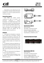
DM-50
Brand: GATT AUDIO Pages: 2

Soundzone SMS1
Brand: JBL Pages: 24

MME239 - Micro DVD Home Theater System
Brand: Magnavox Pages: 39

EXPEDITION XP40iw
Brand: Samson Pages: 2

Go Mic
Brand: Samson Pages: 40

THE KICKBALL
Brand: Blue Microphones Pages: 12

HIF-8892EBT
Brand: Roadstar Pages: 80

1680335
Brand: Speaka Professional Pages: 8

I-WXH 80
Brand: Scott Pages: 13

MS-RA210
Brand: Fuslon Pages: 14

PGA27
Brand: Shure Pages: 14

RS2046
Brand: RCA Pages: 1

591
Brand: Apex Digital Pages: 2

TMR
Brand: Waterous Pages: 4

RCD614
Brand: Curtis Pages: 12

CA-UXF3B
Brand: JVC Pages: 2

RS22163CP
Brand: RCA Pages: 20

VLX
Brand: Samson Pages: 21


