

PASystem_XP40i_Instructions.doc
3/7/2014
pg. 1 of 2
PA System w/ iPod Deck and Wireless Microphone
XP40iW Rear View
Quick Start
Aba Daba Rents
4 3 5 1 A u b u r n B l v d .
S a c r a m e n t o , C A 9 5 8 4 1 - 4 1 5 2
( 9 1 6 ) 4 8 4 - 7 3 6 8 F a x ( 9 1 6 ) 4 8 2 - 2 5 5 2
w w w . a b a d a b a . c o m
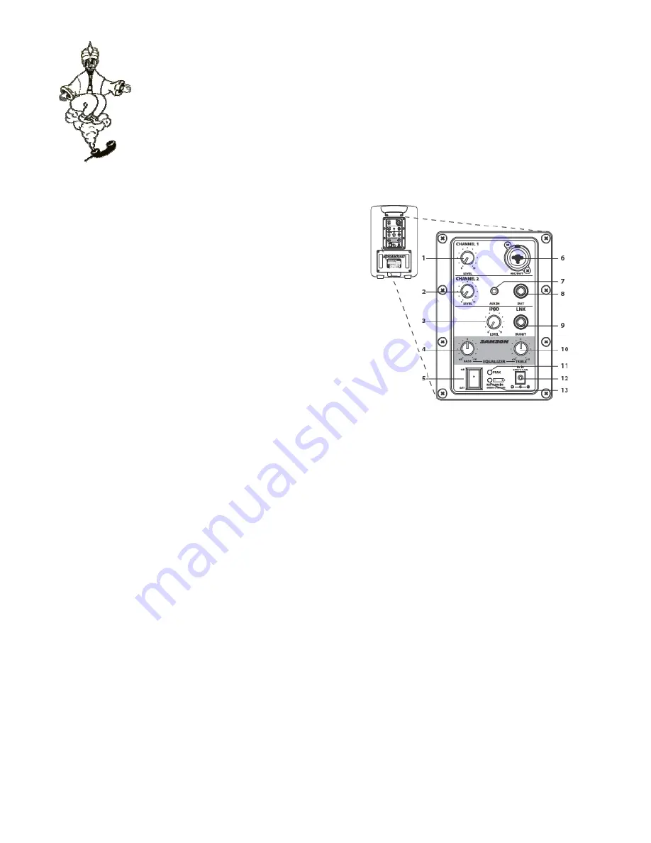
1. LEVEL
(CH1) – Used to control the level of the CHANNEL 1 input
2. LEVEL
(CH2) – Used to control the level of the CHANNEL 2 input.
3. RF
LED
–
Illuminates when an RF signal is detected.
4. LEVEL
(WIRELESS)
– Used to control the level of the wireless microphone.
5. BASS – Controls the low band of the Channel Equalizer, +/- 15 db at 100 Hz.
6. POWER – Switches on the XP40iw’s main power.
7. MIC/INST
(connector) – Combo XLR plus ¼ inch Input for connecting
microphone or Instrument level signals.
8. AUX
IN – 1/8-INCH Auxiliary line input for connecting a Laptop, CD or MP3
player.
9. INSTRUMENT
Input – ¼-inch phone jack connector used to connect
instrument or line level signals.
10. iPod
LEVEL
Used to control the level of the iPod input.
11. LINK – ¼-inch phone jack connector used to link a second XP40iw.
12. TREBLE – Controls the high band of the Channel Equalizer, +/- 15 db at
10kHz.
13. PEAK
LED – The Red LED illuminates at the level where distortion occurs.
14. DC POWER INLET – Connect the supplied standard DC power adapter here.
15. BATTER
LED – Show the status of the battery charge level.
Using a Microphone
•
Be sure that the XP40i’s POWER switch is set the off position.
•
Turn the CHANNEL 1, CHANNEL 2 and iPod LEVEL controls
fully counterclockwise to the off position.
•
Connect the power adapter to an AC socket.
•
Using a standard XLR cable, plug a microphone into the XP40i’s
CHANNEL 1 INPUT.
•
Switch the XP40i’s Power switch to the ON position.
•
While speaking into the microphone, slowly raise the CHANNEL
1 LEVEL control until you have reached the desired level.
Using an Instrument Level Signal
•
Be sure that the XP40i’s POWER switch is set the off position.
•
Turn the LINE and MIC LEVEL controls fully counterclockwise to
the off position.
•
Connect the power adapter to an AC socket.
•
Using a standard ¼ inch cable, connect an instrument level
signal from a guitar or keyboard into the XP40i’s INSTRUMENT
INPUT.
•
Switch the XP40i’s Power switch to the ON position.
•
Now, play your keyboard or guitar while slowly raising the
CHANNEL 2 LEVEL control until you have reached the desired
level.
IMPORTANT NOTE: Be sure to keep the MIC LEVEL control all
the way off if there is no microphone connected.
Vocal Mic.
Keyboard
iPod Playback
•
Turn all the input channels down by rotating the LEVEL
control knobs to their fully counter clockwise position.
Then, set the BASS and TREBILE controls to their 12:00
positions
•
Check that the rear panel POWER switch is set to the OFF
position. Then, plug the supplied power adapter into the
rear panel DC inlet, and then plug the wall socket adapter
into an acceptable power outlet, but don’t turn the unit on
just yet.
•
If your iPod came with a dock adapter install it into the iPod
dock on top of the XP40iw.
•
Next install your iPod into the Xp40iw. Be sure the iPod is
seated all the way in and that it’s making a good
connection in the dock.
•
Now power on your SP40iw system using the rear panel
POWER switch but keep the volume down to start.
•
Now press Play on your favorite tune and adjust the
SP40iw’s rear panel iPod LEVEL control until you reach a
comfortable listening level.


