background image


Version 1.0 


UM20-GN User’s Guide


DiGi Microscope 


Summary of Contents for UM20-GN

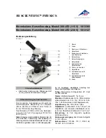
Page 1: ...Version 1 0 UM20 GN User s Guide DiGi Microscope...

Page 2: ......

Page 3: ...mble microscope with stand 2 1 3 IR Remote controller 4 1 4 Microscope menu functions 10 1 5 Microscope introduction 23 1 6 Microscope Focus 26 1 7 Microscope accessory 30 2 Printed Notice 31 2 1 Main...

Page 4: ...onto microscope Item Q ty Item Q ty DiGi Microscope 1 White Balance Card 1 HDMI Cable 1 IR Remote Control 1 USB C 3 0 Cable 1 User s Guide 1 Power adaptor 1 Calibrator 1 S107 Stand 1 Object Lens 4x 1...

Page 5: ...nd 1 2 1 Fix microscope Tighten the microscope onto stand a Refer to Stand assembling instruction for detailed explanation 1 2 2 Start to use microscope Connect the HDMI cable b and adaptor c to HDMI...

Page 6: ...onds 1 3 IR Remote controller The microscope operation and functions is controlled by the IR remote controller 1 Power Turn on off 2 HDMI When in HDMI mode the HDMI cable must connect with the screen...

Page 7: ...Manual focus 7 1 Zoom in Zooms in speed increases when held 7 2 Zoom out Zooms out speed increases when held 7 3 Step zoom in zoom in by steps 7 4 Step zoom out zoom out by steps 8 Autofocus Press on...

Page 8: ...12 Down Choose the next item if Crosshair is ON select other color 13 Left Choose the next value if Crosshair is ON select Line Size 14 Right Choose the last value When MENU function is not turn on pr...

Page 9: ...us Button to switch to standard 4X 10X lens mode 16 1 Area d 16 1 1 FOV Field of View FOV display image on the effective horizontal size of screen 16 1 2 MAG Magnification The magnification size will...

Page 10: ...W are same function as AFS 16 2 5 LED Reference data is not for this model 16 2 6 EV Exposure Value Ex EV 5 means EV is 5 EV 5 means EV is 5 16 2 7 MR Motor Reset 16 2 8 SHA Sharpness Ex SHA SET 5 me...

Page 11: ...e lens focus until clear and choose On Because the white balance is sometimes influenced by external light sources it is recommended to calibrate the white balance if the color seems off or incorrect...

Page 12: ...ss Up and Down to choose item Left and Right to turn on off or adjust parameter Enter means more functions press Menu to enter next function or confirm means no more settings Return to return last pag...

Page 13: ...AGC Auto Gain Control auto control the brightness based on setting when light is not enough 3 SENS UP Only available when item 2 AGC value is larger than 0 use to increase Senor to light s sensibility...

Page 14: ...pecial environment use Defog function to see clear image Below fig for De Fog setting When select AUTO enter the DEFOG Setting 6 1 POS SIZE Adjust de fog position and area 6 2 GRADATION To set gradati...

Page 15: ...ghtness for darker image in back light environment 2 1 LEVEL To adjust brightness level 2 2 AREA Choose the back light compensation area and size 2 3 DEFAULT Return to default setting 2 4 Return Retur...

Page 16: ...to Black 3 4 LEVEL Set Threshold for over exposed image 3 5 DEFAULT Return to factory default setting 3 6 RETURN Return to last page or Save End Menu 4 WDR Wide Dynamic Range WDR allows an imaging sys...

Page 17: ...color 1 AWB Auto white balance 2 ATW Trace white area and auto calibrated 3 AWC SET Semi auto white balance Use to track the white color from current image Same as 1 3 17 operation 4 4200K Suitable f...

Page 18: ...high quality output image and increase file compression See below 1 2D NR LOW MIDDLE HIGH Edge Preserving 2D NR 2 3D NR LOW MIDDLE HIGH Motion Adaptive 3D NR 3 Return Return to last page or Save End...

Page 19: ...FF to freeze image If Freeze function is turn on the 1 2 Mirror function can not be used at the same time 1 2 MIRROR Image rotatory Horizontal or Vertical 1 3 NEG IMAGE Turn On Off Negative image 1 4...

Page 20: ...whenever object moves The lower value gets the higher sensitivity 2 4 COLOR The Area frame color Green Blue White and Red 2 5 TRNAS The Area frame transparency 2 6 ALARM Setup Detected Area s display...

Page 21: ...ast page or Save End Menu 3 LANGUAGES 16 languages are selectable 4 DEFFECT Dead Pixel compensation 4 1 LIVE DPC Dead Pixel Correction Correct the live dead pixel during preview 4 1 1 AGC LEVEL Auto G...

Page 22: ...se do not change this setting 4 2 1 POZ SIZE Choose the compensation area 4 2 2 START Start to do Static Dead Pixel correction 4 2 3 DPC VIEW Show corrected Dead Pixels 4 2 4 LEVEL Set the threshold v...

Page 23: ...RM Firmware version 6 RETURN Return to last page or Save End Menu 1 4 6 ADJUST Image Adjustment 1 SHARPNESS Adjust Sharpness higher value increases the higher contrast along near edges of the image 1...

Page 24: ...Blue GAIN level 2 3 RED GAIN Adjust Red Gain level 2 4 RETURN Return to last page or Save End Menu 3 LSC Lens Shading Correction Use Lens shading correction to average the luminance of image 4 VIDEO O...

Page 25: ...ransparent protection sheet on the IR receiver area 1 IR remote control aiming area f The indicator will blink whenever buttons are pressed If the indicator did not blink means the signal was not deli...

Page 26: ...es forcefully 1 Power i Power adaptor is only compatible with the cord in the box Please do not use other adaptor 2 USB j USB port for PC connection or Firmware update 3 HDMI K The HDMI port is used t...

Page 27: ...25 1 5 3 Stand gear box Assemble the stand and then screw the microscope onto the universal joint l on the gear box l...

Page 28: ...s There are two ways to focus First choose focus distance to adjust the microscope height then tuning focus by remote controller until clear On the contrary first to choose the image sensor position t...

Page 29: ...remote controller or far distance control mode on the application program to focus the image 2 Fixed image sensor position The status bar will show on the screen please refer to Section 1 3 16 Use th...

Page 30: ...have 14 focus sections The sensor position tells the magnification size Mag field of view FOV or working distance WD The below chart is measured on 4 3 ratio on 24 screen it s only a reference data m...

Page 31: ...2 15 1 17 7 21 2 26 5 29 5 33 2 35 4 37 9 Focus section 10 11 12 13 14 15 16 17 18 Sensor position 1280 1240 1190 1130 1095 1055 1015 965 910 WD mm 70 5 65 5 60 0 55 0 52 0 49 5 47 0 44 0 41 5 FOV mm...

Page 32: ...6 FOV mm 2 3 2 2 2 1 2 0 1 9 1 8 1 7 1 6 1 5 Mag X 231 242 253 266 280 295 313 332 354 Focus section 10 11 12 13 14 Sensor position 815 625 400 135 45 WD mm 7 3 7 0 6 7 6 4 6 3 FOV mm 1 4 1 3 1 2 1 1...

Page 33: ...lfunction if it encounters strong collision vibration or distortion 2 1 4 Turn the microscope off before cutting off the power supply do not forced cut off the power supply 2 1 5 Do not face the lens...

Page 34: ...Output 1080P 1920 1080 Pixel image USB 3 0 Port Type C output YUV MJPE format Max res 1080P Focus Control IR remote control Power Supplier Adaptor Output DC 5 0V 2 0A Input AC 100 240V 50 60Hz A C Pow...

Page 35: ...e the device or the device is dropped or damaged please switch off and remove the power supply to avoid fire and electric shock Do not look steadily into Light sources after switching on the host as i...

Page 36: ...34...

Page 37: ...r etc Services caused by any of the following situations in the period of the warranty shall not be provided free of charge 1 Improper use or disassembly repair or refitting 2 Any damages to the devic...

Page 38: ...r Confirmation Stamp is necessary for validation of the Warranty Distributor s seal shall include name of the shop telephone and address Please ask the distributor to fill in the name of the shop addr...

Page 39: ......

Page 40: ...HTTP WWW VITINY COM MicroLinks Technology Corp All rights reserved...

Reviews: