


Preferred Service
SMC-0031
July 2012
This manual is to be used by qualified appliance technicians only.
Viking does not assume any responsibility for property damage
or personal injury for improper service procedures done by an
unqualified person.
Service
Manual
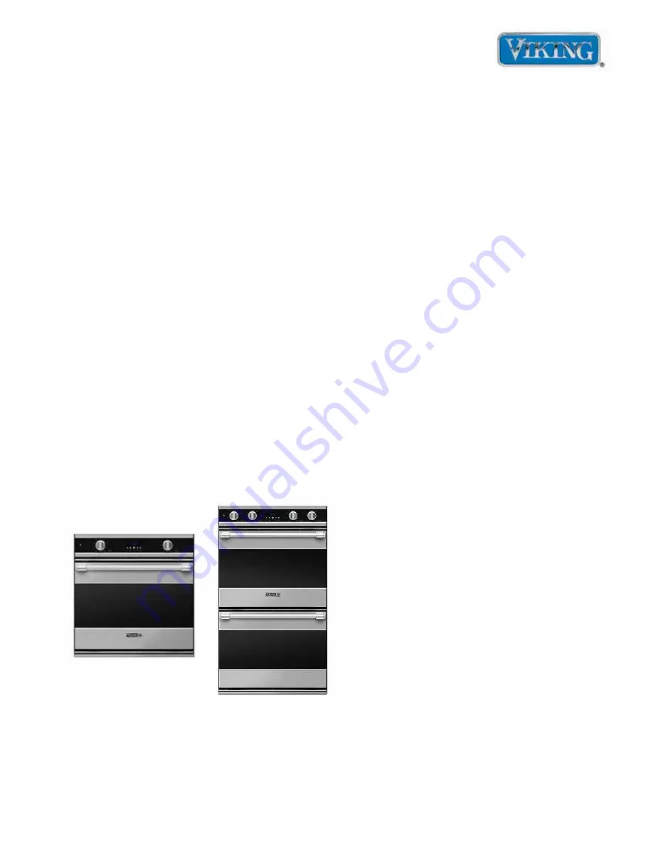
This Base Manual covers general and
specific information including, but not
limited to the following models:
RDSOE306SS
RDDOE306SS
Single
and Double
Wall Oven


