

..
Viglen Getting Started Guide
Omnino 4
Included fittings
Your Omnino 4 has been shipped with a multi-purpose screw pack. You will not need to use all the
screws in the pack to complete this assembly. You will require the screws shown below:
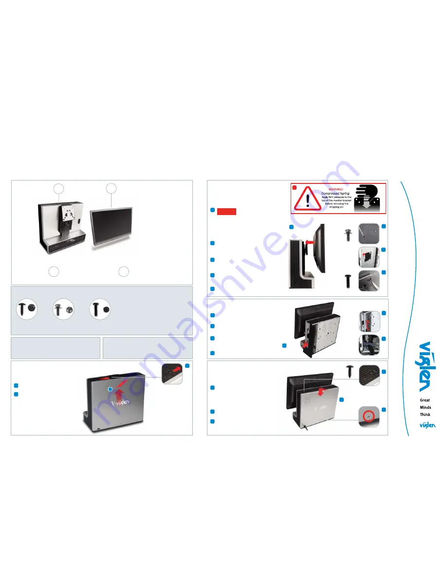
Step 2
Attach the Monitor
Step 3
Connect Cables
Screw A
Screw B
Screw C
( x 1)
( x 2 )
( x 3 )
Tools required
Cross-head (philips-head) screwdriver
Optional security screwdriver (order EMSECDRV from Viglen)
Included cables
Depending on your configuration you will receive one split
power cable for the base unit and monitor and one or more
of the following cables: video, audio.
Start Guide - Omnino 4 (2010-06)
Slide the locking latch to release the back
cover
Slide the back cover up, then pull it away
from the base unit.
Take care when removing the
monitor stand shipping pin.
The monitor stand contains a strong spring under
pressure. Apply firm pressure to the top of the
monitor bracket before pulling the pin out.
Optional:
Fit 1x Screw C in the shipping pin hole
to restrict downward movement of large monitors.
Fix 2x Screw B (lug screw) to the lower VESA
mounting holes in the rear of the monitor. Refer
to your monitor manual for instructions on how to
remove the monitor’s stand.
Unlock the cable window in the base unit and feed
the monitor signal and power cables through.
Place the monitor face down in front of the base
unit and connect the monitor cables.
Lift the monitor onto the monitor stand VESA
bracket and hang the monitor by engaging the lug
screws in the lower holes
Hold the monitor in place and secure it using 2x
Screw C.
CAUTION!
Remove the side panel of the cable bay by
sliding it backwards and lifting it away.
Connect the monitor signal cable, mouse,
keyboard and other accessories.
Secure the mouse, keyboard, power and
other external cables using the cable strap at
the bottom of the cable bay.
Replace the side panel of the cable bay.
Replace the back cover by applying it flat to
the back of the base unit, engaging its lugs
and pushing firmly downwards.
Care should be taken to ensure that all
cables are routed through the cable window
in the bottom of the cover.
Optional:
Fit 1x Security Screw A into the
locking clip to deter unauthorised opening.
Optional:
Fit a Kensington-style locking cable
or clip to lock the cover and secure the
Omnino 4 to the desktop.
1
2
1
2
1
1
2
3
3
2
4
1
1
2
3
3
1
2
1
2
4
5
5
4
3
3
1
2
1
2
Contents
Base Unit
Monitor
2
Step 4
Replace the Back Cover
Step 1
Remove the Back Cover
x2
x2
x1


