background image


R


Installation, 


Maintenance, & Testing Manual
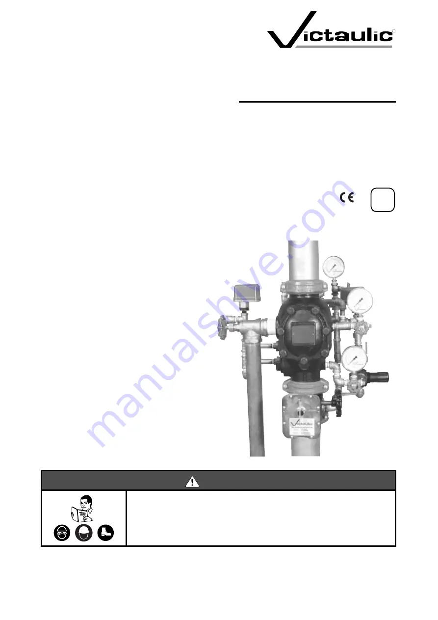
 

Series 756

FireLock


®


 European

Dry Valve Stations


Hang these instructions on the

installed valve for easy future reference.


WARNING


Failure to follow instructions and warnings could cause product failure, resulting in serious personal injury and/or property 
damage.

• Read and understand all instructions before attempting to install, maintain, or test any Victaulic piping products.

• Wear safety glasses, hardhat, and foot protection.

If you need additional copies of any literature, or if you have any questions about the safe installation and operation of this 
product, contact Victaulic Company of Europe, Prijkelstraat 36, 9810 Nazareth, Belgium, Phone: 32-9-381-1500.

VdS

0786

Summary of Contents for FireLock 756 Series

Page 1: ...ng in serious personal injury and or property damage Read and understand all instructions before attempting to install maintain or test any Victaulic piping products Wear safety glasses hardhat and foot protection If you need additional copies of any literature or if you have any questions about the safe installation and operation of this product contact Victaulic Company of Europe Prijkelstraat 3...

Page 2: ...spection 21 Maintenance 23 Removing and Replacing Clapper Seal 23 Removing and Replacing Clapper Assembly 24 Installing Cover Plate Gasket and Cover Plate 25 Cover Bolt Torque Requirements 26 Removing and Replacing Piston Assembly 26 Troubleshooting Series 753 A Dry Actuator Anti Flood Device 27 Troubleshooting Series 746 Dry Accelerator 27 Troubleshooting System 27 Warranty 28 Facilities Location...

Page 3: ...ors can create hazardous working conditions 9 Keep visitors away Keep all visitors a safe distance away from work areas Maintenance and Testing 1 Notify the authority having jurisdiction Always notify the authority having jurisdiction before taking a fire protection system out of service or before performing any maintenance that eliminates the fire protection provided by the system 2 Depressurize ...

Page 4: ...ccelerator adds approxi mately 46 cm onto the top of the Series 753 A Dry Actuator Valve Size Dimensions centimeters Approx Weight Each kg A A1 B C D E F G H I J K L DN100 50 66 63 12 94 00 16 13 30 53 31 00 41 00 8 00 19 50 28 00 43 00 25 64 10 00 67 0 DN150 56 32 71 99 94 00 18 60 34 40 33 00 46 00 15 19 23 00 46 00 20 50 10 00 80 0 The A1 dimension applies only to a valve with the additional Se...

Page 5: ...ce Alarm Line Drain 4 Main System Drain Valve 20 EPS 10 Alarm Pressure Switch 5 Water Supply Pressure Gauge 0 25 Bar 21 Reducer X inch 6 Gauge Valve 22 Series 760 Water Motor Alarm with inch 7 System Pressure Gauge with Mark Pointers 0 16 Bar Strainer 100 mesh Optional 8 Piston Charge Line Ball Valve Lockable Normally Open 23 Series 753 A Dry Actuator Anti Flood Device 9 Piston Charge Line Straine...

Page 6: ... 2 2 Clapper 12 Latch Shaft 3 Clapper Seal 13 Latch Shaft Retaining Bushing Qty 2 4 Seal Ring 14 Piston O Ring 5 Seal Washer 15 Piston 6 Seal Retaining Ring 16 Cover Plate Gasket 7 Bolt Seal 17 Cover Plate 8 Seal Assembly Bolt 18 Cover Plate Bolt Qty 7 9 Clapper Spring 19 Latch 10 Clapper Shaft 20 Latch Spring 1 18 17 2 12 13 13 16 9 20 19 6 5 4 3 10 11 14 11 15 8 7 ...

Page 7: ...ber the seal lifts from its seat Water escapes from the piston charge line of the dry valve thus allowing the piston to retract The dry valve s clapper opens and water flows into the sprinkler system Integral Anti Flood Device After the dry valve operates water from the main water supply enters the air filled trim A Series 748 Ball Check is included in the trim which prevents water from entering t...

Page 8: ...rictor When a rapid loss of system air pressure occurs such as an open sprinkler air escapes from the closing chamber faster than it does from the opening chamber As the sprinkler system s pressure continues to decay a differential pressure develops across the dia phragm When this differential pressure reaches 0 2 0 3 Bar the opening chamber s pressure overcomes the compression spring s closing fo...

Page 9: ...calculated by dividing the sys tem s maximum water pressure by 8 and then adding 0 7 Bar Victaulic Air Maintenance Trim Assembly AMTA COMPRESSOR AND AIR MAINTENANCE TRIM REQUIREMENTS 0 8 1 1 2 1 4 1 6 1 8 2 2 2 2 4 2 6 2 8 10 11 12 13 14 15 16 3 4 1 2 5 6 7 8 9 MAXIMUM WATER SUPPLY PRESSURE BAR PEAK AIR PRESSURE BAR BILL OF MATERIALS Item Description 1 inch Restrictor 2 Slow Fill Ball Valve 3 Air ...

Page 10: ...air maintenance trim is normally installed refer to the trim drawing 2 Due to the large on off differential available for pressure switches that control base mounted compressors adjust the compressor s pressure switch so that the ON contact is at the recommended air supply for the valve Proper Air Supplies for Series 756 Dry Valves Used with Series 753 A Dry Actuators and Series 746 Dry Accelerato...

Page 11: ... to activate at 0 3 Bar be low the minimum air pressure required 3 Wire the alarm pressure switch to activate a water flow alarm 4 Set the alarm pressure switch to activate on a pressure rise of 0 3 0 6 Bar HYDROSTATIC TESTING The Victaulic Series 756 European Dry Valve is manufactured and listed for a maximum working pressure of 16 Bar and is fac tory tested to 41 Bar The station can be hydrostat...

Page 12: ...iston charge line ball valve 8 7 Charge the system with air by turning on the compressor or by opening the fast fill ball valve on the air maintenance de vice 28 fast fill ball valve is shown above Fill the system to the appropriate pressure for the typical water supply pressure in the area 7a Confirm that the system is charging by observing the sys tem pressure gauge 7 If the gauge is not showing...

Page 13: ... fast fill ball valve on the air maintenance device 28 8 Open the slow fill ball valve on the air maintenance device 28 Confirm that the air regulator is set to the proper system pressure 9 If a Series 746 Dry Accelerator is used open the 1 4 turn vent ball valve on the accelerator 14 as shown above 19 17 23 13 NOTICE The Victaulic air regulator is a relief type design Any pressure in the system t...

Page 14: ...line ball valve 8 12 Pull up on the auto drain knob 12 until it is set in the UP position Verify that there is pressure on the piston gauge 11 13 Confirm that the piston charge line pressure 11 is equal to the water supply pressure 5 The piston is now actuated and the clapper will now be set 14 Open the alarm line ball valve 17 14 14 8 CAUTION Take precautions when opening the water supply s main ...

Page 15: ... and start over at step 1 17 Open the water supply s main control valve 2 fully 18 Record the system air pressure 7 water supply pressure 5 and piston charge line pressure 11 19 Ensure all valves are in their normal operating positions refer to table below 20 Notify the authority having jurisdiction remote station alarm monitors and those in the affected area that the system is in service Valve No...

Page 16: ...st on a more frequent basis Verify these require ments by contacting the authority having jurisdiction in your area 1 Notify the authority having jurisdiction remote station alarm monitors and anyone in the affected area that the water flow alarm test will be performed 2 Close the alarm line ball valve 17 3 Open the alarm test line ball valve 18 Confirm that me chanical and electrical alarms provi...

Page 17: ...the authority having jurisdiction if required Water Level and Low Air Alarm Tests The authority having jurisdiction in your area may require the wa ter level and low air alarm tests on a more frequent basis Verify these requirements by contacting the authority having jurisdic tion in your area 1 Notify the authority having jurisdiction remote station alarm monitors and anyone in the affected area ...

Page 18: ...re at which the low air alarm activates 6 Close the system main drain valve 4 7 Open the fast fill ball valve on the air maintenance device 28 Bring the pressure back up to normal system pressure 8 When the proper pressure is established close the fast fill ball valve on the air maintenance device 28 9 Open the slow fill ball valve on the air maintenance device 28 10 If a Series 746 Dry Accelerato...

Page 19: ...valves are in their normal operating posi tions refer to table below 13 Notify the authority having jurisdiction remote station alarm monitors and those in the affected area that the valve is back in service 14 Provide test results to the authority having jurisdiction if required Valve Normal Operating Position Piston Charge Line Ball Valve Open Lockable Alarm Line Ball Valve Open Lockable Alarm T...

Page 20: ...se the piston charge line ball valve 8 10 Perform all steps in the Placing the System in Service section starting on page 11 Full Trip Test Victaulic recommends full trip testing every 3 years This test allows a full flow of water into the sprinkler system therefore this test must be performed in warm weather when there is no chance of freezing conditions NOTE The authority having juris diction in...

Page 21: ...y 6 Continue to run water until it is clear 7 Close the water supply s main control valve 2 8 Close the piston charge line ball valve 8 9 Close the slow fill ball valve on the air maintenance device 28 10 Perform all steps in the Placing the System in Service section starting on page 11 2 8 28 ...

Page 22: ...alves 4 Confirm that no water is flowing from the system main drain valve 4 5 Close the piston charge line ball valve 8 6 Close the slow fill ball valve on the air maintenance device 28 7 If pressure still remains in the piston charge line 11 make sure the auto drain knob 12 is in the down position If necessary push down on the auto drain knob 12 to remove pressure in the piston charge line 11 WAR...

Page 23: ...uctions in the Maintenance section starting on page 23 11 Re install the cover plate by following the Installing Cover Plate Gasket and Cover Plate section starting on page 25 12 Place the system back in service by following the Placing the System in Service section starting on page 11 WARNING Make sure the valve is depressurized and drained before removing the cover plate bolts The cover plate wi...

Page 24: ...evious step Re insert the ring carefully underneath the outer lip of the clapper seal Make sure the smaller diameter of the seal ring is toward the sealing surface of the clapper seal as shown above WARNING Depressurize and drain the piping system before attempting to install remove or adjust any Victaulic piping products Failure to follow this instruction could cause prod uct failure resulting in...

Page 25: ...Installing Cover Plate Gasket and Cover Plate section starting on page 25 Removing and Replacing Clapper Assembly 1 Perform steps 1 8 of the Required Internal Inspection section starting on page 21 2 Remove one clapper shaft retaining bushing from the valve body 3 Remove the clapper shaft as shown above NOTE As the shaft is being removed the clapper spring will drop out of posi tion Keep the clapp...

Page 26: ...er Plate Gasket and Cover Plate 1 Verify that the cover plate gasket is in good condition If the gasket is torn or worn replace it with a new Victaulic sup plied gasket 2 Align the cover plate gasket holes with the cover plate holes 3 Insert one cover bolt through the cover plate and cover gasket to ease alignment 4 Align the cover plate cover plate gasket to the valve Make sure the spring arms ar...

Page 27: ... the System in Service section starting on page 11 Valve Size Torque N m DN 100 136 DN 150 156 WARNING Depressurize and drain the piping system before attempting to install remove or adjust any Victaulic piping products Failure to follow this instruction could cause product failure resulting in serious personal injury and or property damage CAUTION Any activities that require taking the valve out ...

Page 28: ...to all dry accelerator joints and check for leaks Repair any leaks and re test Air decay rate of system is too slow Make sure there are no restrictions in the inspector s test connection If the above procedures do not work contact Victaulic The dry accelerator does not set up properly cannot get pressure on the upper gauge and the button pops up immediately when pressure is introduced Dry accelera...

Page 29: ...MEDY SHALL BE FOR THE REPAIR OR REPLACEMENT OF DEFECTIVE PRODUCTS AS PROVIDED HEREIN THE BUYER AGREES THAT NO OTHER REMEDY INCLUDING BUT NOT LIMITED TO INCIDENTAL OR CONSEQUENTIAL DAMAGES FOR LOST PROFITS LOST SALES INJURY TO PERSON OR PROPERTY OR ANY OTHER INCIDENTAL OR CONSEQUENTIAL LOSS SHALL BE AVAILABLE TO HIM Victaulic neither assumes nor authorizes any person to assume for it any other liab...

Page 30: ...elgium Phone 905 884 7444 Fax 905 884 9774 Phone 32 9 381 15 00 Fax 32 9 380 44 38 e mail viccanada victaulic com e mail viceuro victaulic be VICTAULIC AMERICA LATINA VICTAULIC ASIA PACIFIC P O Box 31 Easton PA USA 18044 0031 541 Orchard Road 14 02 Liat Towers 4901 Kesslersville Road Easton PA USA 18040 Singapore 238881 Phone 610 559 3300 Fax 610 559 3608 Phone 65 6235 3035 Fax 65 6235 0535 e mail...

Reviews: