

1
Installation
6
Access
to the
mobile
viewer
5
Network
Setting
\
\
Basic Layout
\
\
Rear View
J
Since the cable quality may affect directly to the video quality depending on the distance between the camera and DVR, it is recommended to consult an authorized installer when installing the DVR.
\
\
Network Connection
\
\
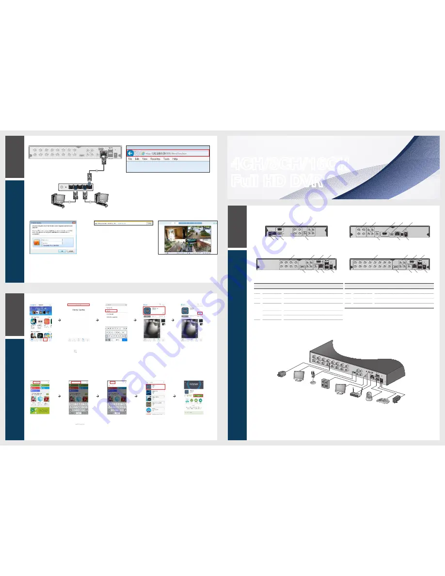
To access the Web Viewer
2.
When the login dialog appears, enter the user name
and password.
The default ID and password
- User name : ADMIN
- Password : 1234
Be aware when you enter the ID whether it is upper or lower case
3.
Click the upper warning bar to install the ActiveX
before enabling the add-in function.
4.
When the security warning window appears, click
<
Install
>.
5.
When the ActiveX is installed completely, you will
see the live screen.
For more information about using the Web viewer, refer to
the user manual.
1.
Open the browser and enter the IP address of DVR, or enter the URL address in
the address bar.
ex) if you use the DDNS of the DVR:
http://00115f123456.dvrlink.net :8080
If you do use the IP address of the DVR:
http://192.168.0.210 : 8080
For more information about the router and network settings, refer to the user
manual of the respective product.
4CH/8CH/16CH
Full HD DVR
Quick Guide
\
\
How to download and access the Android-specific viewer
1.
From your
smart phone,
access the
Market.
2.
From the top
menu bar, click
<
>.
3.
Type "nViewer"
in the search
bar.
4.
Select "nViewer"
to install it.
5.
When done,
select "nViewer"
again and
install it.
\
\
How to download and access the iOS-specific viewer
1.
From your iPhone,
access App store.
2.
From the lower
menu bar, click
< >.
3.
Type "nViewer" in
the search bar.
4.
Select "nViewer"
to install it.
5.
When done,
select "nViewer"
again to run it.
4 channels (1HDD)
8 channels (2HDD)
4 channels (2HDD)
16 channels (2HDD)
No.
Name
Description
a
VIDEO IN
Video input terminal for cameras.
b
AUDIO IN
Port for audio input.
c
VGA
VGA monitor video output port.
d
RS485
Ports for communication with external devices such as PTZ
camera and system keyboard.
RELAY
Relay Terminal output port.
ALARM IN
Alarm input signal port.
No.
Name
Description
e
HD MONITOR
HD monitor video output port.
f
AUDIO OUT
Port for speaker connection.
g
ETHERNET
Network port for connection to the Internet, router or hub.
h
DC 12V
Power input port. Connect to a 12V adaptor.
DC 12V
VGA
1
1
3
2
2
3
4
4
HD MONITOR
VIDEO IN
AUDIO
OUT
AUDIO IN
ENTHERNET
h
g
e
a
b
c
f
1
3
1
3
2
4
2
4
VIDEO IN
AUDIO IN
AUDIO
OUT
VGA
HD MONITOR ETHERNET
DC 12V
RS485
D+
D-
c
e
d
b
a
f
g
h
1
2
3
4
5
6
7
8
9
10
11
12
13
14
15
16
VIDEO IN
RS485
RELAY
D+
NC
NO
COM
AUDIO
OUT
VGA
HD MONITOR
ETHERNET
DC 12V
1
3
2
4
AUDIO IN
ALARM IN
IN1 IN2
IN3 IN4
GND
b
a
e
f
g
h
c
d
1
3
5
7
2
4
6
8
VIDEO IN
RS485
RELAY
D+
NC
NO
COM
AUDIO
OUT
VGA
HD MONITOR
ETHERNET
DC 12V
1
3
2
4
AUDIO IN
ALARM IN
IN1 IN2
IN3 IN4
GND
b
a
e
f
g
h
c
d
1
2
3
4
5
6
7
8
9
10
11
12
13
14
15
16
VIDEO IN
RS485
RELAY
D+
NC
NO
COM
AUDIO
OUT
HD MONITOR
ETHERNET
DC 12V
1
3
2
4
AUDIO IN
ALARM IN IN1 IN2
IN3 IN4
GND
DC 12V
Power
Camera
Sensor
IP Router
or HUB
Control
Devices
VGA
MONITOR
HD
MONITOR
Speaker
MIC
1
2
3
4
5
6
7
8
9
10
11
12
13
14
15
16
VIDEO IN
RS485
RELAY
D+
NC
NO
COM
AUDIO
OUT
VGA
HD MONITOR
ETHERNET
DC 12V
1
3
2
4
AUDIO IN
ALARM IN
IN1 IN2
IN3 IN4
GND
RS485
4
WAN
RESET
PWR
3
2
1
Local PC
Local PC
Broadband router
or hub


