VESDA VLQ-100, Product Manual
The VESDA VLQ-100 is a cutting-edge, state-of-the-art fire detection system. Ensure maximum protection by downloading the free Product Manual from our website. This comprehensive manual provides valuable insights and instructions for optimizing the VLQ-100's performance. Safeguard your premises efficiently; visit our website to download the manual today!
Share
Download


Reviews:
No comments
Related manuals for VLQ-100

SOLUNA
Brand: La Crosse Technology Pages: 12
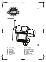
481872
Brand: Jamestown Pages: 52

FURM50000
Brand: Abus Pages: 32

VS235XR
Brand: Uniden Pages: 8

GEMC-WL-SMK
Brand: NAPCO Pages: 4

Virtual Key 2UK
Brand: Clifford Pages: 8

Polaris 4
Brand: Clifford Pages: 9

SuperNova
Brand: Clifford Pages: 15

Concept 600
Brand: Clifford Pages: 13

GP500
Brand: Clifford Pages: 28

PRO-9776i
Brand: Audiovox Electronics Pages: 12

IP43
Brand: iHome Pages: 14

iP40
Brand: iHome Pages: 14

iBTW450
Brand: iHome Pages: 16

iH41
Brand: iHome Pages: 12

iKN95
Brand: iHome Pages: 24

RC 40
Brand: Hama Pages: 13

106941
Brand: Hama Pages: 16


