background image

2021/10/08 00:37

1/12

FFC-100 Fiber Frequency Comb Quick Start Guide

Product Manuals - https://www.vescent.com/manuals/

FFC-100 Fiber Frequency Comb Quick Start
Guide

Model No. FFC-100-100 and FFC-100-200
Document Last Updated on 2021/10/06 23:13

Please read 

Limited Warranty

 and 

General Warnings and Cautions

 prior to operating the FFC-100.
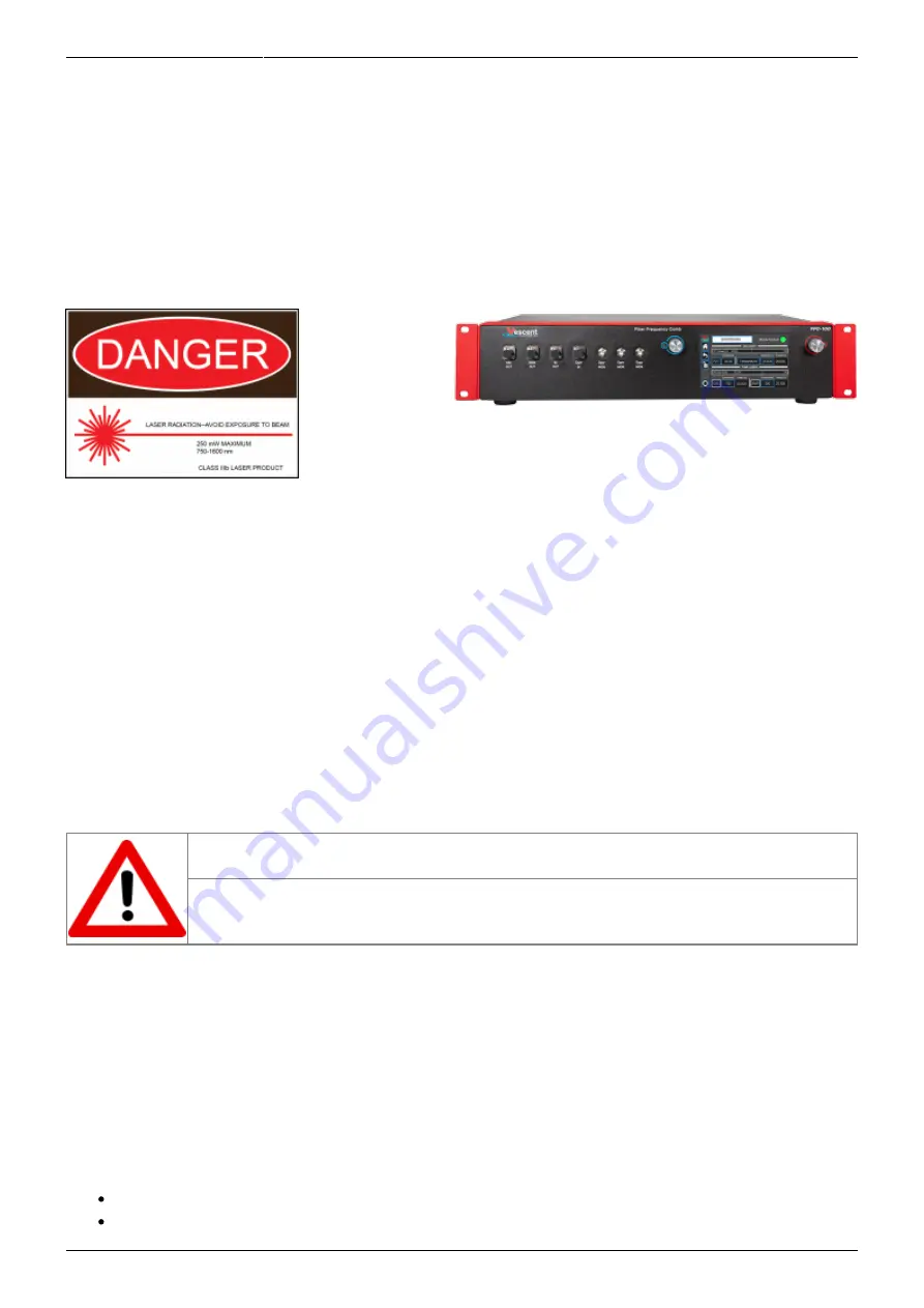
  Fig. 1: The

FFC-100 Fiber Frequency Comb

Useful Links

Vescent manuals page

.

FFC-100 API

.

FFC-100 web page

.

Github page for FFC-100 firmware revisions


FFC-100 Manual

Please check back for added functionality. Contact 

sales [at] vescent [dot] com

 for questions and

corrections, or to request added functionality.

Notice

Do not block the airflow vents on the side of the chassis or the fan inputs & outputs
on either the FFC-100 or the SLICE-FPGA.
The mode-lock indicator on the GUI front panel cannot detect CW breakthrough. Keep
the oscillator current within the range specified in your product's final test
documentation or CoC.

Operating the FFC

This document provides instructions on how to operate the Vescent Photonics FFC-100 when
controlled by the Vescent SLICE-FPGA.

Purchase Includes

FFC-100 rack-mountable Fiber Frequency Comb module
Power cord for your country (if known)

Summary of Contents for FFC-100

Page 1: ...lease check back for added functionality Contact sales at vescent dot com for questions and corrections or to request added functionality Notice Do not block the airflow vents on the side of the chassis or the fan inputs outputs on either the FFC 100 or the SLICE FPGA The mode lock indicator on the GUI front panel cannot detect CW breakthrough Keep the oscillator current within the range specified i...

Page 2: ...ut line voltages It will accept input line voltages within the ranges shown in table 2 Parameter Value Units Input Line Voltage 100 240 VAC Frequency 50 60 Hz Phase 1 phase User serviceable fuse 1 T 2 0 A L 250V Tab 2 Input Voltage Specifications Proper Usage If this instrument is used in a manner not specified by the manufacturer in this manual or other relevant literature protection provided by th...

Page 3: ...cal connection diagram Click for larger image Parameter Rating ƒopt Power Input 1 5 mW max Tab 3 Operating Parameters FFC 100 Operation FFC Start Up GUI Touch the System Off button at the top of the front panel screen figure 3 to bring up a drop 1 down menu Select Standby figure 4 to turn on temperature control of the pump diodes and oscillator cavity ...

Page 4: ...37 Fig 3 The FFC 100 GUI in off state Fig 4 Select Standby laser state Once the temperature servos have stabilized and Standby has stopped blinking touch the 2 Standby drop down menu figure 5 and select Laser On figure 6 The FFC should commence lasing and the Mode locked indicator should turn green figure 7 Fig 5 The FFC 100 GUI in Standby mode ...

Page 5: ...lding down the Osc touch screen button and 3 typing in a desired set point figure 8 or briefly pressing the button and using the two control knobs left changes digits right adjusts values to set a desired value Fig 8 Adjust oscillator current via keypad Cavity temperature can be adjusted in the same way 4 Touch the PZT touch screen button figure 9 to bring up a drop down menu and select Full 5 Range ...

Page 6: ...ce laser such as the Rio Planex If you have not already done so install Python and the FPGA software for controlling the SLICE FPGA dual Offset Phase Lock Servo Software Startup Open a WinPython command window and navigate to the folder GUI and Firmware 1 Start the SLICE FPGA control GUI by typing python XEM_GUI3_VPv4 py figure 10 2 Fig 10 Start FPGA GUI from Terminal A start up menu should appear fi...

Page 7: ...Frequency Comb Quick Start Guide Product Manuals https www vescent com manuals Fig 11 FPGA GUI Start Screen Navigate to the Filter Settings tab and select Narrowband 6MHz for both DDC0 and DDC1 4 figure 12 Fig 12 Set Loop Filter Bandwidth ...

Page 8: ... data in the Baseband IQ plot is circular figure 13 This centers the beat note near the reference frequency It is also possible to adjust the FFC 100 oscillator current on its front panel to make this adjustment Fig 13 Centering ƒ CEO on reference frequency Baseband IQ optimization Press the Lock button figure 14 top middle If the system doesn t lock change the VCO sign 2 to the opposite polarity to...

Page 9: ...Manuals https www vescent com manuals Fig 14 Locking ƒ CEO Locking ƒ opt Navigate to the Optical Lock window Center the beat note near the reference frequency 1 adjust the Offset DAC 1 slider or your reference laser frequency until you see a circular Baseband IQ diagram figure 15 ...

Page 10: ...s www vescent com manuals Printed on 2021 10 08 00 37 Fig 15 Centerig ƒ opt on reference frequency Baseband IQ optimization Press the Lock button figure 16 If ƒopt doesn t lock change the VCO sign to the opposite 2 polarity and try again If the system continues to not lock lower the Kp value ...

Page 11: ...vided in a near term software update Open your computer s device manager from the control panel and find the COM port number for 1 STMicroelectronics Never assume that this number is the same as previous times If it doesn t appear make sure your computer is connected to the FFC Navigate to the Slow Loop tab in the GUI and enter the COM port number into FFC COM 2 Port The PZT setpoint is set to an i...

Page 12: ...www vescent com manuals doku php id ffc 100 https www vescent com manuals Printed on 2021 10 08 00 37 From https www vescent com manuals Product Manuals Permanent link https www vescent com manuals doku php id ffc 100 Last update 2021 10 06 23 13 ...

Reviews: