


AVOCENT® LONGVIEW™ 5000 SERIES
HIGH PERFORMANCE KVM EXTENDER SYSTEMS
Quick Installation Guide
590-1519-501A
1
The LongView™ 5000 series high
performance KVM extender
system provides the fastest way to
extend high quality video, audio,
USB and serial data across your
network.
SUPPORTED HARDWARE
LongView™ 5020 extenders
support most standard speakers/
headsets, microphones, USB
keyboards, USB mice and an
additional video channel.
INSTALLATION
After completing the following
installation steps, please refer to
your LongView™ 5000 Series
Installer/User Guide for additional
information, including video and
audio configuration details.
NOTE:
Ensure your computer is
turned off before completing the
following steps.
1. Connecting transmitter
video
Connect a display port cable
from the primary video port on
the computer to DP port 1 on
the rear of the transmitter.
Connect a second display port
cable from the secondary video
port on the computer to DP
port 2 on the rear of the
transmitter.
2. Connecting other
transmitter peripherals
Using a USB cable no longer
than three meters, plug the
USB connector from the cable
into the USB port labeled Link
A on the rear of the transmitter.
Connect the other end to a
USB port on the host
computer.
NOTE:
Link A provides low/full
speed USB to the three USB
ports (all labeled A) located on
the front panel of the receiver.
The optional Link B provides
Hi-Speed USB to the single
USB port (labeled USB 2.0)
located on the front panel of
the receiver.
Low/full speed USB devices
can also be used on the Link B
port; the transfer speed will be
automatically reduced. The
Link A ports support USB
keyboards and mice only.
If desired, attach an additional
USB cable to a vacant USB
(v2.0) port on the host
computer and insert the other
end into the USB port labeled
Link B on the rear of the
transmitter.
3. Connecting audio to the
transmitter
The LongView 5020 extender
system supports both analog
and digital audio. The Line In
port on the transmitter and
the Line Out port on the
receiver can accept either 3.5
mm analog jacks or mini-
TOSLINK optical fiber
connectors.
ANALOG AUDIO
Use a 3.5 mm audio jack cable
to connect the Line In
port
on the transmitter to the analog
Line Out or speaker port of the
host computer.
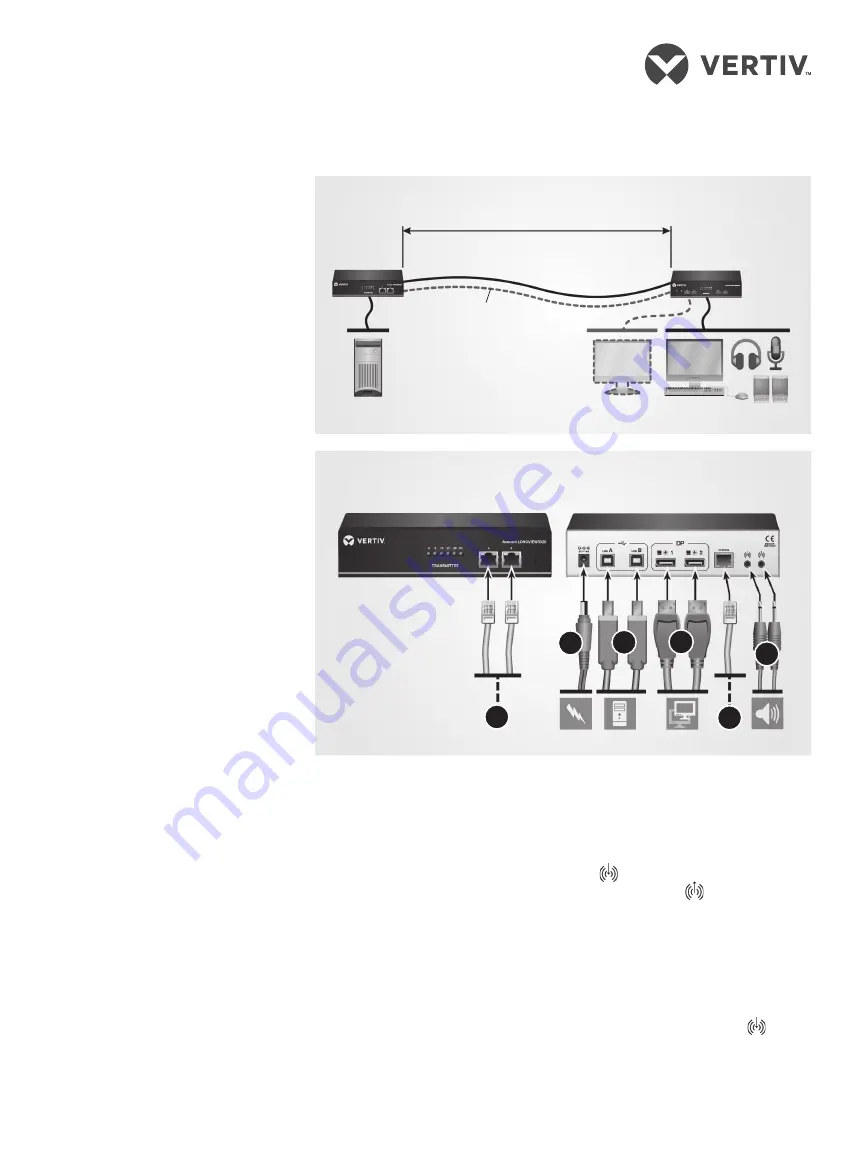
LongView™ Extender System Overview
LongView™ Extender Configuration (Transmitter)
Transmitter
Extender
Receiver
Extender
Up to 492 ft. (150 meters) separation
Additional video
channel
Additional
CAT x link
Front
Back
1
3
2
4
6
5


