Velleman K8400, User Manual
The Velleman K8400 is an innovative 3D printer with a wide range of capabilities. To get the most out of your K8400, make sure to download the free User Manual from our website. This comprehensive manual provides step-by-step instructions and troubleshooting tips for optimal printing results.
Share
Download


Reviews:
No comments
Related manuals for K8400

C910
Brand: Oki Pages: 282

P2
Brand: MakerPi Pages: 21

Saddle Finisher-AF2
Brand: Canon Pages: 244

C831dn
Brand: Oki Pages: 48

4070 FX
Brand: Wasp Pages: 86

CR-6 Max
Brand: Creality Pages: 24

OkiPos 407II
Brand: Oki Pages: 8

SignJet JS310 Series
Brand: GRAPHTEC Pages: 83

PagePro 8
Brand: Minolta Pages: 227

TRP-100
Brand: Tandy Pages: 83

SP410
Brand: iDPRT Pages: 41

SP 4510dn
Brand: Ricoh Pages: 955
5700i - EPL B/W Laser Printer
Brand: Epson Pages: 33
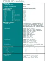
2180 - LQ B/W Dot-matrix Printer
Brand: Epson Pages: 2

2190 - FX B/W Dot-matrix Printer
Brand: Epson Pages: 2

2200 - Stylus Photo Color Inkjet Printer
Brand: Epson Pages: 62
24-PIN DOT MATRIX PRINTER LQ-680PRO
Brand: Epson Pages: 3

221
Brand: Epson Pages: 2


