Velleman DVM890, User Manual
The Velleman DVM890 is a cutting-edge digital multimeter designed for efficient electrical measurements. Enhance your troubleshooting and DIY projects with this reliable device. Easily operate and utilize its diverse features by accessing the comprehensive User Manual, available for free download exclusively from manualshive.com. Get yours today!
Share
Download


Reviews:
No comments
Related manuals for DVM890

Data Multiplexer Explore 1665
Brand: Alcatel-Lucent Pages: 408

MT1877
Brand: Major tech Pages: 28

7D13
Brand: Tektronix Pages: 96

6000
Brand: ACT Pages: 16

RC831-240E
Brand: Raisecom Pages: 29

VC 350E
Brand: Conrad Pages: 91

ms8217
Brand: Mastech Pages: 21

ET3260
Brand: East Tester Pages: 51

MT565
Brand: Major tech Pages: 32

DMM7512
Brand: Keithley Pages: 13

SL206
Brand: AEMC Pages: 16

25221
Brand: Maxwell Digital Multimeters Pages: 39
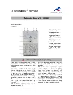
Escola 10
Brand: 3B SCIENTIFIC PHYSICS Pages: 6

1013526
Brand: 3B SCIENTIFIC PHYSICS Pages: 30

VC-335
Brand: VOLTCRAFT Pages: 104

VC 260
Brand: VOLTCRAFT Pages: 93

VC-12A
Brand: VOLTCRAFT Pages: 106

1386328
Brand: VOLTCRAFT Pages: 130


