VC VCSBC6438, Operating Manual
The VC VCSBC6438 Operating Manual is available for free download on our website. This comprehensive manual provides detailed instructions and key information for effectively using the VC VCSBC6438 product. Enhance your user experience by accessing the manual from manualshive.com and unlock all the features and functionalities of this remarkable product.
Share
Download


Reviews:
No comments
Related manuals for VCSBC6438

S3
Brand: Halo Pages: 3

NXT rio
Brand: IDS Pages: 29

QT SERIES
Brand: Q-See Pages: 12

V-VGACON
Brand: Ken A Vision Pages: 2

ICA-W7100
Brand: Planet Pages: 10

SI-C600N
Brand: Meiji Techno Pages: 16

AF-S NIKKOR 18-35mm f_3.5-4.5G ED
Brand: Nikkor Pages: 2

DiMAGE G500
Brand: Konica Minolta Pages: 126

SHC500
Brand: Brinno Pages: 16

S7iDPF10
Brand: Sandstrom Pages: 24

47 SERIES
Brand: Safety Vision Pages: 20

TruVision Multi-Imager
Brand: Interlogix Pages: 22

LR6-BAT
Brand: Lightrein Pages: 20

DV087
Brand: Conbrov Pages: 10

4716
Brand: InterTest Pages: 20

BG-MAESTRO
Brand: BZB Gear Pages: 32

Zoom 6000
Brand: Navitar Pages: 4
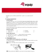
610027
Brand: Equip Pages: 8


