


Installation, Operating &
Maintenance Instructions
605403ED
Edition 2017-11-24
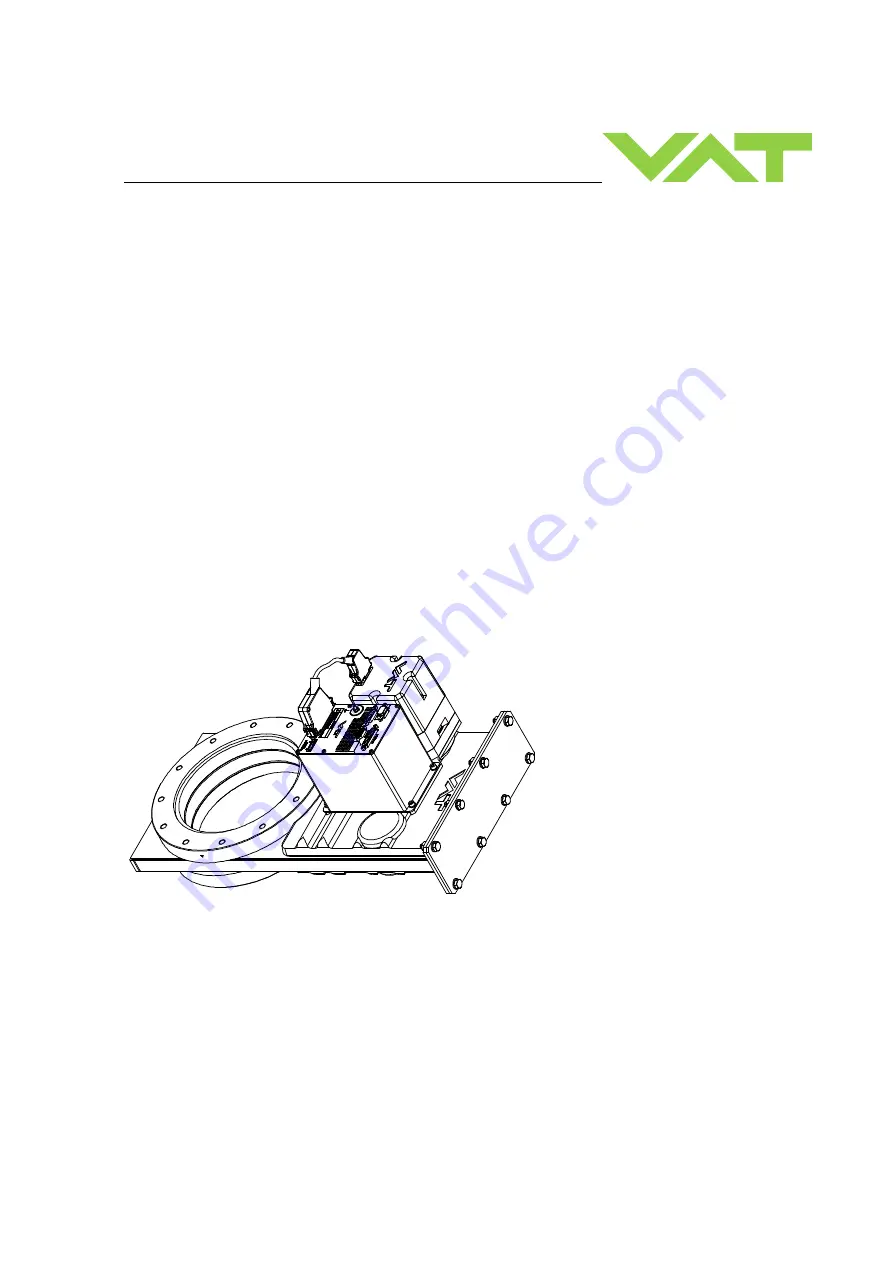
Control gate valve
with Logic interface
Series 642
DN 63-400 mm (I.D. 2.5“ - 16")
This manual is valid for the valve ordering number(s):
642 . . - . .GC- . . . .
(1 sensor input)
642 . . - . .GE- . . . .
(2 sensor inputs)
642 . . - . .AC- . . . .
(1 sensor input /
±
15V SPS)
642 . . - . .AE- . . . .
(2 sensor inputs /
±
15V SPS)
642 . . - . .HC- . . . .
(1 sensor input / PFO)
642 . . - . .HE- . . . .
(2 sensor inputs / PFO)
642 . . - . .CC- . . . .
(1 sensor input /
±
15V SPS / PFO)
642 . . - . .CE- . . . .
(2 sensor inputs /
±
15V SPS / PFO)
SPS = Sensor Power Supply
PFO = Power Failure Option
configured with firmware 600P.1G.00.06…08
Sample picture


