ValueStore US Portable Ultrasound V12, User Manual
The ValueStore US Portable Ultrasound V12 is a powerful and compact ultrasound device perfect for medical professionals on-the-go. Easily access the user manual for free download at manualshive.com to learn how to operate this cutting-edge technology for accurate and efficient imaging.
Share
Download


Reviews:
No comments
Related manuals for Portable Ultrasound V12

s-max sella
Brand: AAT Pages: 44
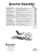
Kinetec Spectra Essential
Brand: Patterson Medical Pages: 104

KUMO MINI
Brand: MIKO Pages: 8

Air Solo
Brand: b-intense Pages: 30

Posh Domaine Semi-Recessed Wall Hung
Brand: Reece Pages: 8

R9344
Brand: Geberit Pages: 28

Allyn FF-102
Brand: Kraus Pages: 12

Pet Zipline GTV00-16550
Brand: Premier Pet Pages: 4

063-3850-8
Brand: Danze Pages: 8

ILBAGNOALESSI 8.2890.1
Brand: Laufen Pages: 8

StartEdge 31 369
Brand: Grohe Pages: 18

Sinus Body
Brand: i-like Metaphysik Pages: 40

PAW SPA PETJET
Brand: Oxygenics Pages: 4

HydroBoost HTHBWF-HRFSER
Brand: Halsey Taylor Pages: 4

MRTL246 BRISBANE 250
Brand: R.T. LARGE Pages: 3

2030039562
Brand: Franke Pages: 20

TL4129
Brand: Pet Gear Pages: 4

AeroChamber Plus Flow-Vu aVHC
Brand: Monaghan Pages: 2


