vacuubrand BVC control, Instruction Manual
The Vacuubrand BVC control is a powerful vacuum controller for precise pressure control in laboratory applications. Ensure optimal performance by downloading the free Instruction Manual from our website. Get the manual to understand how to maximize the capabilities of this innovative product. Download now from manualshive.com.
Share
Download


Reviews:
No comments
Related manuals for BVC control

Pronto 012
Brand: Rheem Pages: 28

41.733.80
Brand: EINHELL Pages: 44

CH 406
Brand: Homa Pages: 11

55234
Brand: O'Clair Pages: 138

Sandpiper S05
Brand: Warren rupp Pages: 22

altherma ERHQ014BAV3
Brand: Daikin Pages: 32

2600401
Brand: Raypak Pages: 40

Preferred 225B
Brand: Bryant Pages: 54

CronoBloc BL Series
Brand: Wilo Pages: 43

29993227
Brand: Wilo Pages: 16

Amana VSZ14
Brand: Maytag Pages: 12

RSH Series
Brand: Danfoss Pages: 4

ZPK Series
Brand: Zehnder Pumpen Pages: 34

Polypropylene Rotary Drum Pump
Brand: Pressol Pages: 3

HPS4HDX
Brand: Pentair Hydromatic Pages: 20
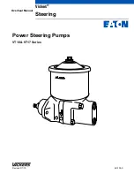
Vickers VT16
Brand: Eaton Pages: 11

R E U - K M2635FFUDHD-E
Brand: Rinnai Pages: 64

bwa BP501
Brand: Balboa Pages: 2


