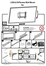
background image

For 26-52" TV

If you have any questions along the way, just give us a call

1-800-460-0956 or mail to [email protected].

We’re ready to help!

WFM009-01

INSTRUCTION MANUAL

R

USA-A0

Summary of Contents for WFM009-01

Page 1: ...For 26 52 TV If you have any questions along the way just give us a call 1 800 460 0956 or mail to customerservice x mount com We re ready to help WFM009 01 INSTRUCTION MANUAL R USA A0 ...

Page 2: ... intended for use only with the maximum weights indicated Use with products heavier than the maximum weights indicated may result in collapse of the mount and its accessories causing possible injury Socket Wrench 1 2 13mm Electric Drill Screw driver Level Pencil Tape Measure Stud Finder 5 32 4mm Wood Drill Bit 3 8 10mm Masonry Drill Bit Hammer This product is designed for use in wood stud solid co...

Page 3: ...3 TV INTERFACE WALL PLATE SIDE VIEW MAX 400mm 15 75 MAX 400mm 15 75 MIN 75mm 2 95 430mm 16 93 28mm 1 10 MIN 75mm 2 95 3 D 472mm 18 58 408mm 16 306mm 12 204mm 8 102mm 4 222mm 8 7 162mm 6 38 26mm 1 ...

Page 4: ... WARNING This product contains small items that could be a choking hazard if swallowed Before starting assembly verify all parts are included and undamaged If any parts are missing or damaged do not return the damaged item to your dealer contact Customer Service Never use damaged parts NOTE Not all hardware included will be used Parts and Hardware for STEP 1 ...

Page 5: ...g Bolt x4 Allen Key x1 5 Contact us at telephone 1 800 460 0956 USA or mail to customerservice x mount com to have these additional pieces shipped directly to you Concrete Wall Anchor 4pcs Parts and Hardware for STEP 2 ...

Page 6: ...6 M8 M6 M4 1 1 Select TV Screws ...

Page 7: ...1 2 Figure out the suitable position of brackets 7 INSTALL UP DOWN IF NEEDED TV BRACKETS MUST BE LEVEL LOW MOUNTING HOLES HIGH MOUNTING HOLES ...

Page 8: ... to combine M6 M8 c e f screws with 2 5mm spacers i you have to remove the inner circle Yes choose suitable screws washers and spacers 1 4 Attach the TV Plate No No choose suitable screws and washers 1 3 Need Spacer 8 ...

Page 9: ... Maximum horizontal space between fasteners 16 in 406 mm Stud center must be verified 1 Locate your studs Verify and mark the center of the stud by finding the stud edges using a thin nail or an edge to edge stud finder 2 Position the wall plate unit at your desired height and line up the holes with your stud center line Level the wall plate and mark the hole locations Again find another wood stud...

Page 10: ... 2 36 in 60 mm Be sure to drill into the center of the studs CAUTION Improper use could reduce the holding power of the lag bolt DO NOT over tighten the lag bolts Go to STEP 3 on PAGE 13 5 32 4mm 10 4 Install wall plate using four lag bolts Tighten the lag bolts only until they are pulled firmly against the wall plate No ...

Page 11: ... onto the concrete surface 1 Position the wall plate unit on the wall at your desired height Level the wall plate and mark the hole locations 2 Drill four pilot holes using a 3 8 in 10 mm diameter masonry drill bit IMPORTANT Pilot holes must be drilled to a depth of 2 36 in 60 mm Minimum solid concrete thickness 8 in 203 mm ...

Page 12: ...f the lag bolt DO NOT over tighten the lag bolts Concrete Wall Anchor Not included 4 Insert wall plate using four lag bolts Tighten the lag bolts only until they are pulled firmly against the wall plate Please contact us at telephone 1 800 460 0956 USA or mail to customerservice x mount com to have these additional pieces shipped directly to you No ...

Page 13: ...Before hanging TV please try to pull the mount to make sure that it has been assembled on the wall tightly 13 100lbs 45 5kg ...

Page 14: ...Pull down TV 1 2 14 ...

Page 15: ...Pull down the straps 15 ...

Reviews: