background image

SRM12

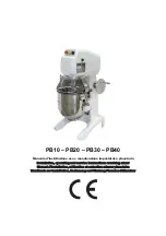
PLANETARY MIXER

PARTS & SERVICE MANUAL

Persons under the age of 18 are not permitted to operate or have access to this

equipment per U.S. Dept. Of Labor Employment Standards Administration Sheet No. ESA913

SRM12  REV B

SRM12 

6(59,&(

 REV B

Summary of Contents for SRM12

Page 1: ...IXER PARTS SERVICE MANUAL Persons under the age of 18 are not permitted to operate or have access to this equipment per U S Dept Of Labor Employment Standards Administration Sheet No ESA913 SRM12 REV B SRM12 6 59 REV B ...

Page 2: ...BLY OPTIONAL 3 7 POWER TAKE OFF PARTS LIST 3 8 INPUT ASSEMBLY 3 9 INPUT ASSEMBLY PARTS LIST 3 10 VERTICAL SHAFT ASSEMBLY 3 11 VERTICAL SHAFT ASSEMBLY PARTS LIST 3 12 REASSEMBLY 3 11 4 BOWL SUPPORT ASSEMBLY BOWL SUPPORT REMOVAL AND DISASSEMBLY 4 1 BOWL SUPPORT ASSEMBLY PARTS LIST 4 2 5 BOWL LIFT ASSEMBLY REMOVAL AND DISASSEMBLY 5 1 BOWL LIFT ASSEMBLY PARTS LIST 5 2 6 SPEED CONTROL ASSEMBLY REMOVAL ...

Page 3: ...EMBLY 3 10 FIGURE 8 VERTICAL SHAFT ASSEMBLY 3 12 FIGURE 9 TRANSMISSION SHAFT ASSEMBLY 3 14 FIGURE 10 BOWL SUPPORT ASSEMBLY 4 2 FIGURE 11 BOWL LIFT ASSEMBLY 5 2 FIGURE 12 SPEED CONTROL ASSEMBLY 6 2 FIGURE 13 DRIVE ASSEMBLY 7 4 FIGURE 14 MIXER HOUSING ASSEMBLY 8 2 FIGURE 15 CUTAWAY VIEW OF MIXER 9 1 FIGURE 16A WIRING DIAGRAM 115 208 240V 60HZ 1PH 220 240V 50 60HZ 1PH 9 2 FIGURE 16B WIRING DIAGRAM 46...

Page 4: ...KET 3 BOWL SUPPORT PIN 12 SPEED CONTROL LEVER 4 BEATER HEAD SHAFT 13 TIMER OPTIONAL 5 INGREDIENT CHUTE 14 SPEED INDICATOR LABEL 6 SWING RING SAFETY GUARD 15 START PUSH BUTTON GREEN 7 MAGNET 16 STOP PUSH BUTTON RED 8 PTO HUB 17 BOWL LIFT HANDLE 9 THUMB SCREW 18 REAR ACCESS PANEL 19 BOWL SCRAPER SHAFT Page 9 ...

Page 5: ...place defective part 2 3 With mixer running slowly move speed control lever fully forward then backward to re engage belt 3 Agitator stalls during mixing 3 1 Mixer bowl is overloaded 3 2 Speed is set to high for the mix 3 3 Loose belt 3 4 Contamination of belt with grease 3 1 Adjust contents of bowl 3 2 Shift speed lower till action rotates smoothly 3 3 Readjust pulley center distance to tighten b...

Page 6: ... Remove dents or replace bowl 7 2 Adjust bowl height 8 Excessive noise 8 1 Gears need to be repacked with grease 8 2 Badly worn or frayed drive belt 8 3 Attachments hitting bowl 8 4 Overloaded mixing bowl 8 1 Locate source by inspection and repack with grease 8 2 Replace belt 8 3 Inspect for cause in items 6 7 above 8 4 Adjust contents of bowl Page 1 2 ...

Page 7: ... Check the belt for proper tension The outer edge of the belt should be flush with the outer diam eter of the variable speed pulley Figure 13 15 If not adjust it by loosening the jam nut Fig ure 13 21 and turning the connecting rod Figure 12 11 until the outer edge of the belt is flush with the outer diameter of the variable speed pulley Retighten the jam nut f Plug in the electrical power supply ...

Page 8: ...ater on the beater head shaft Figure 1 1 b Raise the bowl support to the up position c Check the clearance between the bottom of the bowl and the lowest point of the batter beater The clearance should be 3 16 inch plus or minus 1 16 inch d If adjustment is required disconnect the electrical power supply cord loosen the hex head cap screws Figure 10 13 and raise or lower the bowl until the correct ...

Page 9: ...e mixer WARNING NEVER WORK ON THE TRANSMISSION WITH THE MIXER RUNNING IT IS RECOMMENDED THAT THE ELECTRICAL SERVICE POWER CORD BE DISCON NECTED TO PREVENT ACCIDENTAL START UP LUBRICATION INSTRUCTIONS FIGURE 2 Molykote BR2 Plus B Internal Gear C machine oil B Bowl Lift Medium 30 weight Slide A Grease yearly with Oil yearly C Grease every 500 hours of operation with food grade grease Bowl Lift Beari...

Page 10: ...screw in back Before removing the top cover DISCONNECT THE ELECTRICAL POWER CORD Remove the screw in the rear lift the rear of the cover and push it forward about 2 inches and lift it off b Reinstall the top cover in the reverse of the above procedures using care to insure that the cover sits squarely and uniformly on the mixer housing Rear Access Panel Top Cover Screw Top Cover Page 2 4 ...

Page 11: ... heavy and must be supported prior to removing it Remove the four 1 2 20 hex head cap screws Figure 3 8 securing the transmission housing to the mixer housing Remove the transmission assembly and pace it on a workbench 6 Remove the transmission cover Figure 3 2 by removing the four phillips pan head screws Figure 3 3 and sliding it towards the rear and lifting up 7 Rotate the gear train by hand an...

Page 12: ...r Split Lock 10 6 7 8800022 Foam Strip 1 8 1200057 Screw Hex Hd Cap 1 2 20 X 1 4 9 1200085 Washer Split Lock 1 2 4 10 1200084 Washer Flat 1 2 4 11 4400194 Pin Dowel 1 1012116A Internal Gear Kit Includes 5 6 12 13 12 1200440 Screw Socket Head Cap 10 32 X 1 4 13 1012116 Gear Internal 1 1012439A Magnet Kit Includes 14 15 14 1012439 Magnet 2 15 1012438 Holder Magnet 2 1012447A Transmission Wrap Assemb...

Page 13: ...mbly using the two jack screws if necessary 2 With tool T1201 remove the drive pin Figure 4 3 3 Remove the retaining ring 9 beater head pinion gear 8 and the key 4 from the beater head shaft NOTE If a gear requires replacement always replace it s mating gear Jack Screws 3 8 24 Cap Screw NOTE left hand thread Page 3 3 ...

Page 14: ...118 Retaining Ring Internal 1 8 1012114 Pinion Gear Beater Head 1 9 1200120 Retaining Ring External 3 10 8900038 Screw Socket Hd Set 3 8 16 X 1 1 4 2 11 1020002 Ring Splash 1 12 4400269 Label Rotation 1 13 4400499 Washer 7 16 1 14 1200051 Screw Hex Hd Cap SS 3 8 24 X 1 1 4 LH 1 15 1200400 Pin Roll 1 16 1000438 Shaft Bowl Scraper 1 17 1200110 Pin Bowl Scraper 1 Figure 4 Beater Head Assembly Page 3 ...

Page 15: ... the spur gear 10 and key 12 from the shaft 2 Remove the three 1 4 20 hex head cap screws 5 14 Washers 3 4 deflector 2 and withdraw the bevel gear drive shaft assembly from the transmission housing Bevel Gear 1 4 20 Hex Head Cap Screws Spur Gear Housing Bevel Gear Bevel Gear Shaft Bevel Gear Drive Shaft Assembly Without PTO standard Page 3 5 ...

Page 16: ...3 1200075 Flat Washer 1 4 1 4 4400005 Lock Washer 1 4 3 5 1200022H Hex Hd Cap Screw 1 4 20 X 1 1 6 1030019 Bearing 2 7 1200117 Retaining Ring Internal 1 8 1012309 Gear Bevel 1 9 1012429 Shaft Bevel Gear 1 10 1020004 Gear Spur 1 11 1200119 Retaining Ring External 5 12 1200113 Key Woodruff 9 1 13 1200103 Roll Pin 5 16 X 1 1 7 1 14 1200025H Hex Hd Cap Screw 1 4 20 X 3 4 2 Page 3 6 ...

Page 17: ...the spur gear 15 and key 14 from the shaft 2 Remove the three 1 4 20 hex head cap screws 9 18 Washers 7 8 deflector 6 and withdraw the power take off assembly from the transmission housing Bevel Gear 1 4 20 Hex Head Cap Screws Spur Gear Page 3 7 Power take off assembly Power Take Off Housing Bevel Gear Power Take Off Shaft ...

Page 18: ... 1024417 Lubrication Deflector 1 7 1200075 Washer Flat 1 4 1 8 4400005 Washer Lock 1 4 3 9 1200022H Screw Hex Hd Cap 1 4 20 X 1 1 10 1030019 Bearing 2 11 1200103 Roll Pin 5 16 X 1 1 4 1 12 1012309 Gear Bevel 1 13 1012320 Shaft PTO 1 14 1200113 Key Woodruff Key 9 1 15 1020004 Gear Spur 1 16 1200119 Retaining Ring External 5 17 1200117 Retaining Ring Internal 1 18 1200025H Screw Hex Hd Cap 1 4 20 X ...

Page 19: ...y from the transmission housing 2 Remove the retaining ring 1 and remove the bearing 2 from the input shaft assembly 3 Remove one retaining ring 3 pinion gear 4 and woodruff key 7 from the input shaft assembly Retaining Ring Page 3 9 Input Assembly Input Pinion Gear Bearing Input Shaft Retaining Ring ...

Page 20: ... 1 3 1200119 Retaining Ring External 3 4 1020010 Gear Pinion 1 5 1030019 Bearing 6204LL 1 6 1200117 Retaining Ring Internal 1 7 1200113 Key Woodruff 9 1 8 1012322 Shaft Input 1 9 4400230 Key Square 3 16 X 1 1 2 1 10 4400141 Nut Kep 1 4 20 2 11 1200075 Washer Flat 1 4 2 12 1012306 Bearing Flange 1 13 1200025H Screw Hex Hd Cap 1 4 20 X 3 4 2 Page 3 10 ...

Page 21: ...re 8 4 from the vertical shaft 2 2 Invert the transmission housing on a suitable support and press the vertical shaft assembly from the transmission housing 3 Remove the pin 3 and press the bevel gear 1 from the vertical shaft assembly bevel gear Page 3 11 ...

Page 22: ...ription Qty 1012521 Vertical Shaft Assembly Includes All 1 1012311 Gear Bevel 1 2 1012434 Shaft Vertical 1 3 4400022 Pin Roll 5 16 X 1 1 2 1 4 1200113 Key Woodruff 9 1 5 1030019 Bearing 2 6 1200117 Retaining Ring Internal 1 7 8800042 Spacer 1 Page 3 12 ...

Page 23: ...ring c Reinstall the power take off assembly into the transmission housing install the grease deflector and washers and tighten the three screws Reinstall the spur gear and key on the PTO shaft and install the retaining ring 4 Reassemble and reinstall the beater head assembly 5 The transmission should be progressively checked for smooth operation while on the workbench by turning each assembly as ...

Page 24: ...Transmission Cover Assembly Transmission Housing PTO Spur Gear Vertical Shaft Assembly Assembly Input Shaft Assembly Beater Head PTO Assembly TRANSMISSION SHAFTS ASSEMBLY FIGURE 9 Page 3 14 ...

Page 25: ...hex head cap screws and washers 9 10 and remove the two gibs 8 Remove the bowl support 1 and the slide cover 3 CAUTION The bowl support must be held while the screws 10 are being removed to prevent it from falling 5 Remove the six Kep nuts and washers and remove the rails 6 Lubricate the sliding surfaces with grease 7 Reassemble in the reverse order NOTE Plastic shims may exist between the bowl su...

Page 26: ...des 3 4 3 1012431 Cover Movable Slide 1 4 4400278 Rubber Strip 2 1012430A Bowl Lift Frame Assembly Includes 5 13 5 1012430 Yoke 1 6 1012243 Pin Yoke 1 7 1200121 Retaining Ring External 2 8 1012422 Gibb Bowl Lift 2 9 1200077 Washer Lock 5 16 4 10 1200039 Screw Hex Hd Cap 5 16 18 X 3 4 4 11 1200075 Washer Flat 1 4 2 12 4400005 Washer Lock 1 4 2 13 4400155 Screw Hex Hd Cap 1 4 20 X 1 2 2 Page 4 2 ...

Page 27: ...sen the set screw in the collar 8 and pull the bowl lift lever from the mixer housing 6 Remove the nuts and washers 5 6 7 from the bearings 4 and remove the bearing 7 Clean and inspect all sliding surfaces for excessive wear 8 Replace any assemblies showing excessive wear 9 Lubricate the sliding surfaces with grease 10 Reassemble and reinstall the bowl lift and bowl support in the reverse of the a...

Page 28: ...304A Bowl Lift Bearing Assembly Includes 3 8 3 1200301 Washer Nylon 5 8 1 4 1012304 Bearing Flange 2 5 1200076 Washer Flat 10 4 6 4400065 Washer Lock 10 4 7 1200060 Nut Hex 10 32 4 8 1012305 Collar Shaft 1 1012317A Bowl Lift Cam Assembly Includes 9 12 9 1012317 Cam Assembly Bowl Lift 1 10 1200425 Screw Phillips Flat Hd 1 4 20 X 1 1 11 1200121 Retaining Ring External 1 12 1012352 Link Connector 1 P...

Page 29: ...ts and washers 6 7 holding the speed control housing 5 to the mixer housing and remove the speed control assembly 7 Pull the cam assembly 10 from the speed control housing 8 Remove the two screws 14 and remove the detent disk 16 REASSEMBLY 9 Reassemble the speed control in the reverse of the above procedure Grease the cam assembly shaft and detent disk during assembly with MolyKote BR2 Plus or gen...

Page 30: ...200156 Washer Spring 5 8 2 9 1200304 Screw Socket Hd Set 10 32 X 3 4 2 10 1012359 Cam Assembly Speed Control 1 1012329A Connecting Rod Assembly Includes 11 12 22 23 11 1012329 Connecting Rod Speed Control 1 12 1012202 Rod End 3 8 24 LH 1 13 1200121 Retaining Ring External 2 1023222A Detent Disk Assembly Includes 14 20 14 1200471 Screw Socket Hd Cap 10 32 X 1 2 2 15 4400065 Washer Split Lock 10 2 1...

Page 31: ... 3 and rails 1 11 With the motor rotated so the shaft is pointed up remove the motor from the mixer housing 12 Remove the connection cover plate from the end of the motor and disconnect the motor cord 13 Loosen the set screw and remove the vari speed pulley 15 from the motor shaft 14 Remove the nuts and washers 4 5 and remove the motor from the motor mount 2 REASSEMBLY 15 Reassemble the motor asse...

Page 32: ...Page 7 2 Strap and Rail Vari Speed Pulley Motor Mount Belt Retainer Motor Cord Set Screws Screws Connecting Rod Assembly Driven Pulley Motor Cord Connections Contactor ...

Page 33: ...09 Starter 220 240V 50HZ 1PH Europe Only 1 7100040 Starter 115V 60HZ 1PH Canada Only 1 7100119 Starter 380V 50HZ 3PH Europe Only 1 10 7100010 Mount Contactor 1 11 7100107 Strain Relief 1 12 1023240 Retainer Belt 1 13 1020500 Pulley Driven 1 14 1012357 Belt 1 15 1012373 Pulley Vari Speed 1 16 8800200 Cord Electric 115V 60HZ 1PH 100V 50 60HZ 1PH 1 8800201 Cord Electric 230V 60HZ 1PH 220 240V 50HZ 1P...

Page 34: ...DRIVE ASSEMBLY FIGURE 13 Page 7 4 21 22 ...

Page 35: ...00103 Switch Bowl lift 1 26 1200432 Screw Hex Head Cap 4 40 x 3 4 2 27 1012374 Panel Rear Access 1 28 1200012 Screw Phillips Pan Head 10 32 x 1 2 6 1200452 Screw Security Option 6 29 8800022 Foam Strip 55 30 7100123 Switch Guard 2 31 4400348 Label Speed control 1 32 7100027 Timer 15 minute Optional 1 33 4400310 Label Start Stop without timer 1 4400311 Label Start Stop Timer Optional 1 34 4400079 S...

Page 36: ...4 10 31 11 12 21 37 5 40 30 16 2 35 15 42 3 7 29 9 23 6 28 27 23 36 34 1 32 39 13 33 8 18 14 41 38 21 17 A 19 21 20 SCALE 1 4 DETAIL A 23 22 25 24 26 Page 8 2 HOUSING ASSEMBLY FIGURE 14 ...

Page 37: ...12 QUART MIXER CUTAWAY VIEW FIGURE 15 Page 9 1 ...

Page 38: ...30V 60HZ 1PH L1 L2 GND W8 W9 W7 W6 W5 W2 W1 COLORED PATTERNED WIRES ARE NOT FOR REFERENCE BUT FOR EASE OF USE OF THIS DIAGRAM CW1 W3 W4 CW2 WIRING PACKAGE 8800234 NOTES ATTACH AMP 925552 2 1 ATTACH MOLEX 19002 0025 1 4 F 2 ATTACH MOLEX 19001 0009 3 16 M 3 ATTACH MOLEX 19002 0029 3 16 F 4 MATERIAL 1015TEW CSA AND 5 UL APPROVED TO BE PACKAGED IN SEALED 6 PLASTIC BAG WITH PART NUMBER LABEL PART NUMBE...

Page 39: ...UMBER GA SEE NOTE LENGTH END A SEE NOTE END B SEE NOTE COLOR 8800234 W1 16 5 13 1 3 WHITE W2 16 5 13 2 4 BLACK W3 16 5 6 2 2 WHITE W4 16 5 6 2 2 RED W5 16 5 19 1 2 RED W6 16 5 2 1 2 1 1 BLACK W7 16 5 19 1 2 WHITE W8 16 5 21 1 1 RED W9 16 5 22 1 4 WHITE W10 16 5 12 1 1 WHITE W11 16 5 12 1 1 WHITE W12 16 5 12 1 1 WHITE PART OF CONTACTOR CW1 16 5 2 1 2 1 1 RED CW2 16 5 7 1 1 RED CW3 16 5 7 1 1 RED CW...

Page 40: ... LABEL PART NUMBER WIRE NUMBER GA SEE NOTE LENGTH END A SEE NOTE END B SEE NOTE COLOR 8800234 W1 16 5 13 1 3 WHITE W2 16 5 13 2 4 BLACK W3 16 5 6 2 2 WHITE W4 16 5 6 2 2 RED W5 16 5 19 1 2 RED W6 16 5 2 1 2 1 1 BLACK W7 16 5 19 1 2 WHITE W8 16 5 21 1 1 RED W9 16 5 22 1 4 WHITE W10 16 5 12 1 1 WHITE W11 16 5 12 1 1 WHITE W12 16 5 12 1 1 WHITE PART OF CONTACTOR CW1 16 5 2 1 2 1 1 RED CW2 16 5 7 1 1 ...

Page 41: ...TOLL FREE ORDERING FAX 1 800 356 5614 3 Old Rockingham Road Salem N H 03079 2140 Telephone 603 893 6191 Fax 1 603 893 1249 ...

Reviews: