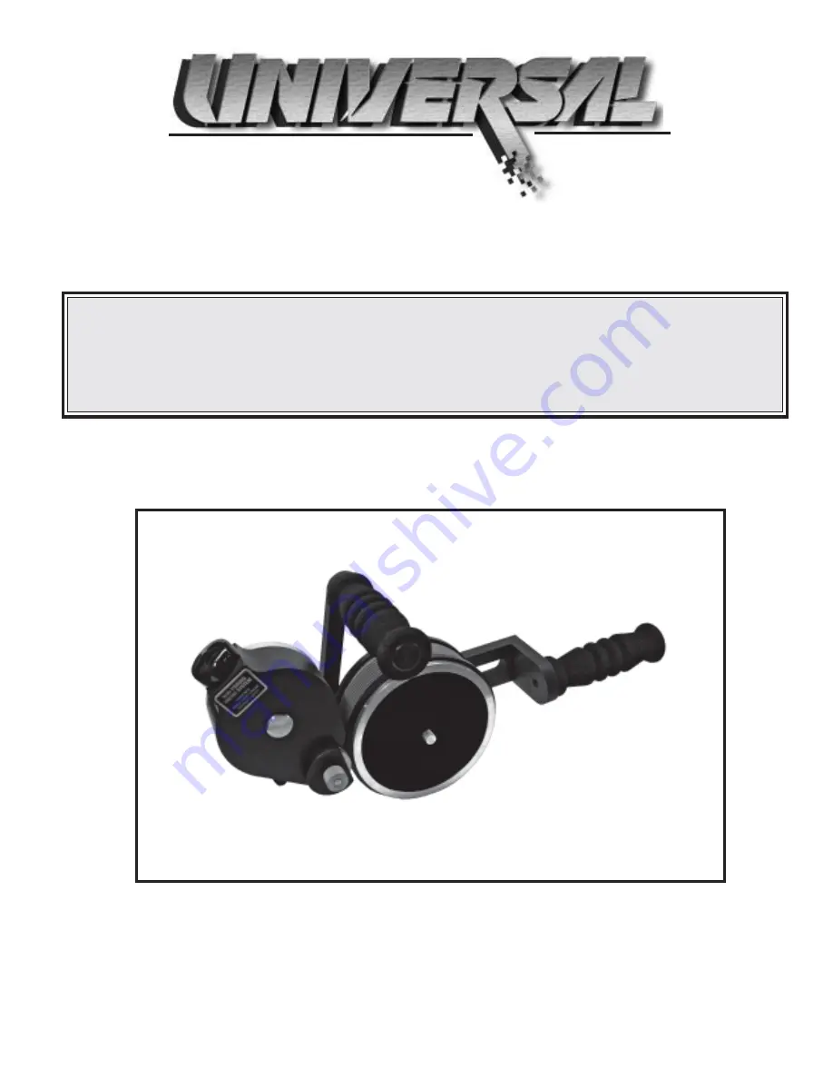
background image

1

NON-POROUS

LARGE CAPACITY HAND PRINTERS

ALL MODELS

UNIVERSAL STENCILING & MARKING SYSTEMS, INC.

P.O. BOX 871 - ST. PETERSBURG, FLORIDA 33731 USA

PH: (727) 894-3027   FAX: (727) 821-7944

E-Mail: [email protected]  Website:  www.universal-marking.com

STENCILING & MARKING                SYSTEMS

HPLNP-22115

OWNER’S MANUAL

INSTALLATION - OPERATION - MAINTENANCE

Summary of Contents for HPL-100NI-NP

Page 1: ...STENCILING MARKING SYSTEMS INC P O BOX 871 ST PETERSBURG FLORIDA 33731 USA PH 727 894 3027 FAX 727 821 7944 E Mail sales universal marking com Website www universal marking com STENCILING MARKING SYSTEMS HPLNP 22115 OWNER S MANUAL INSTALLATION OPERATION MAINTENANCE ...

Page 2: ...roducts are manufactured to exacting standards and every available step has been taken to assure your complete satisfaction It is most important for best results that you read and carefully follow the instructions contained in this manual Failure to do so may result in unsatisfactory performance damage to the equipment and personal injury LIMITED WARRANTY UNIVERSAL Non Porous Large Capicity Hand P...

Page 3: ...ack anodized finish for corrosion resistance 6 Permanently lubricated sealed ball bearings which provide for extremely accurate low friction drum rotation 7 Stainless steel shafts for durability even in harsh environments 8 Indexing mechanism with dual compression springs mounted over stainless steel guide rods minimizes spring breakage and provides unsurpassed indexing speed and accuracy The Univ...

Page 4: ...3 LBS 3 19 KG MAXIMUM DIE SIZE US STANDARD 1 7 RIBS X 16 15 16 LENGTH MAXIMUM DIE SIZE METRIC CODERS ONLY 25 4 MM 7 RIBS X 430 2 MM LENGTH PRINT DRUM CIRCUMFERENCE APPROXIMATELY 18 457 MM MEASURED AT DIE FACE 17 19 436 6 MM 16 41 416 8 MM 6 71 170 4 MM 3 68 93 5 MM 1 04 26 4 MM 8 45 214 6 MM 5 74 145 8 MM ...

Page 5: ... 3 73 KG MAXIMUM DIE SIZE US STANDARD 1 15 16 14 RIBS X 16 15 16 LENGTH MAXIMUM DIE SIZE METRIC CODERS ONLY 49 2 MM 13 RIBS X 430 2 MM LENGTH PRINT DRUM CIRCUMFERENCE APPROXIMATELY 18 457 MM MEASURED AT DIE FACE 17 19 436 6 MM 16 41 416 8 MM 6 71 170 4 MM 5 58 141 7 MM 1 95 49 5 MM 8 45 214 6 MM 5 74 145 8 MM ...

Page 6: ...ction to non compatible solvents in the ink could cause serious problems with the performance of your coder Inks containing MEK or petroleum solvents such as Xylol or Toulene are not compatible The dry XF neoprene ink roll measures 3 425 86 99 mm OD After thoroughly saturating the ink roll with ink the roll should not exceed 3 500 88 90 mm OD SELECTING AN APPROPRIATE INK Universal s Non Porous Ink...

Page 7: ...ifferences the print drums for Metric dies are machined to a slightly different diameter from the U S versions The coder model numbers on Metric coders will have a T suffix and the Metric Drum Covers have a distinct pink color Universal HPL Non Porous Hand Printers are designed to use RIBtype printing dies which have a molded rib backing The ribs on the back of the die snap into mating ribs in the...

Page 8: ...eview of your printing requirements will determine the best choice of ink rolls for your particular application FIGURE 4 Unless otherwise specified all new HPL Non Porous Printers are supplied with XF Neoprene Ink Rolls FIGURE 5 TYPE MT INK ROLLS Type MT Ink Rolls are disposable pre inked rolls which provide excellent color density and adhesion on most materials These disposable rolls yield up to ...

Page 9: ... down on the ink roll you are forcing the air out of the roll material which allows the ink to be absorbed It is important to the performance of the printer that the ink roll is fully saturated but not dripping wet For a 1 1 8 face roll pour approximately 4 ozs of ink into the container for a 2 face roll pour approximately 8 ozs FIGURE 6 FIGURE 7 FIGURE 8 Universal HPL Non Porous Hand Printers are...

Page 10: ...Drive Wheel Cover has a very loose fit Note that one edge of the Drive Wheel Cover is flat and is aligned towards the print drum During reassembly this flat edge must be replaced in the same position Rollers that have been pre inked at the factory are normally slightly oversaturated with ink to compensate for potential solvent loss during shipping and storage If you received a pre inked ink roll w...

Page 11: ...blot excess ink from the sides of the roll with a dry paper towel before installation The Transfer Roll Surface is a finely engraved Delrin plastic material which can be easily scratched When assembled the Transfer Roll resides in a very close fitting cavity in the Inking System Cover Carefully pull the Inking System Cover directly away from the Baseplate until it clears the Transfer Roll to preve...

Page 12: ... Inking System Cover in place 8 Install the ink roll on the Ink Roll Axle by aligning the end of the rod or pencil with the end of the axle and pushing the roll onto the axle 9 Immediately replace the Inking System Cover D by carefully guiding the cover over the Transfer Roll G Try not to let the cover contact the surface of the Transfer Roll to prevent scratching Make sure the Cover is seated pro...

Page 13: ...g a small amount of liquid detergent Lightly moisten the back of the printing die and then immediately press the die into the drum cover Do not apply too much liquid or the dies will slip during printing Note Do not apply silicone oil or any other lubricating agent to the rib backing or the dies will not hold properly during printing 12 Replace the Cover Retaining Knob C and lightly tighten Do not...

Page 14: ...e Eccentric Knob in small increments and observe the face of the printing dies for signs of ink between each adjustment 1 With the Printing Dies installed on the print drum rotate the print drum to a position where the printing dies will contact the transfer roll Then loosen the position adjusting knob and move the transfer roll into contact with the face of the printing dies Tighten the position ...

Page 15: ...the ink roll When the print drum is placed against the surface of the part and pushed forward the drum begins to rotate in a counter clockwise direction The printing die travels a short distance and then contacts the transfer roll where ink is applied to the die face When the die contacts the part the mark is applied FIGURE 25 PRINTING DIE POSITIONING FOR INDEXING APPLICATIONS QUICK START LEADING ...

Page 16: ...ng abrasive 1 To clean dust and ink residue from the surface of the transfer roll first remove it from the coder Lightly saturate a soft cotton cloth with the appropriate ink solvent and gently rub the surface of the roll until it is clean CLEANING THE CODER Warning Most of the ink solvents used for cleaning are flammable liquids Follow all safety precautions recommended by the manufacturer during...

Page 17: ...gment in the ink to the surface of the material being printed As the ink begins to dry this binder becomes tacky or sticky While in this stage of the drying process the tack on the dies will tend to pick up both airborne dust and any dust or dirt on the surface of the material being printed When this happens the dies should be cleaned or replaced The easiest method of cleaning the dies requires th...

Page 18: ... Nylon Tip Set Screw located in the top rim of the Print Drum and remove the dust cover FIGURE 31 3 Using a small screwdriver remove the two E Rings from the stainless steel posts to enable removal of the spring block assembly 2 To relieve the spring tension on the index mechanism rotate the Print Drum approximately 3 4 turn The Index Compression Springs will now be in the fully extended relaxed p...

Page 19: ...ional turn as indicated in Step 5 above 7 The print drum can now be lifted off the axle 1 Holding onto the Index Assembly Block A pull the Index Assembly Block C off the guide shafts Remove the Drum Index Springs 2 Install new Index Springs over the stainless steel guide shafts and replace Index Block C 3 Reinstall the Index Spring Assembly in the Print Drum with the large end of the white bushing...

Page 20: ... from the Print Drum roll down the Drum Cover directly behind the Index Block to expose the Index Assembly Mounting Screw Using a screw driver turn the Mounting Screw in a clockwise direction until the Index Block becomes loose and can be removed If the Indexing Assembly Block B is removed during disassembly it must be realigned using the following procedure 3 Install the Index Ring by threading i...

Page 21: ... a flat block of metal or wood across the top of the Index Ring While holding the block in place raise Index Block B up to contact the bottom of the alignment block FIGURE 49 4 If the Brass Tip Set Screw is not pointing in the direction shown in Figure 47 rotate the Index Ring in a Counter Clockwise Direction until it points in the direction shown 5 Tighten the Brass tip Set Screw securely to prev...

Page 22: ...22 HPL NP PRINTER ASSEMBLY 5 2 6 7 8 9 10 11 13 14 15 16 12 1 4 3 ...

Page 23: ...Y METRIC 10 11 12 13 14 15 16 CF 05 CM 13 CM 04 CF 04 1 1 1 HPL 005 HPL 006 HPL 002 1 1 1 1 8 PRINT DRUM AXLE 2 PRINT DRUM AXLE BACK FRAME SET SCREW 8 32 X 3 16 LG N T S DUST COVER W KNURLED KNOB KNURLEDRETAININGKNOB SET SCREW 1 4 20 X 3 8 LG B T S 1 1 5 8 1 1 4 2 SIDEFRAME QTY REQUIRED 1 2 3 HPL 001 MRM CL20 HPL HA KEY NO PARTNUMBER DESCRIPTION MC 02 HP 04 1 1 2 SCREW 1 4 20 X 5 8 LG SOC HD CAP 3...

Page 24: ...1T CO 02S CB 04 CLP BL2T CLP HPL 100 RIBtype DRUM COVER CLP HPL 200 RIBtype DRUM COVER PRINTDRUMBEARING CLP HPL 100 RIBtype DRUM COVER METRIC CLP HPL 200 RIBtype DRUM COVER METRIC BEARER RING CLP BL1 CLP BL2 PRINT DRUMS ONLYAVAILABLE IN COMPLETE PRINT DRUM ASSEMBLIES SEE PAGES 22 23 KEY 13 ...

Page 25: ...MBLY BLOCK B DRUMINDEXSPRING INDEXASSEMBLY BLOCK C SET SCREW 1 4 20 BTSS INDEX RINGASSEMBLY INDEX PLUNGERASSEMBLY INDEX RAMP SCREW 10 32 X 1 2 SHC HLP 100SERIES NP XC1 NP XC2 HLP 200SERIES 1 1 8 XF NEOPRENE INK ROLL DRY 2 XF NEOPRENE INK ROLL DRY HPL NP SERIES REPLACEMENT INK ROLLS CLP SERIES PARTNUMBER DESCRIPTION HPL NP INDEXING ASSEMBLY 1 2 3 4 5 6 7 8 9 10 11 NP MT1 P1 1 BLACK TYPE MT INK ROLL...

Page 26: ...26 HPL NON POROUS INKING SYSTEM 1 2 3 4 5 6 7 8 9 10 17 16 15 14 13 12 11 ...

Page 27: ...OLL DRY 2 XF NEOPRENE INK ROLL DRY NP XC2 NP MT1 P1 1 BLACK TYPE MT INK ROLL NP MT2 P1 2 BLACK TYPE MT INK ROLL 9 10 12 13 14 15 17 11 1 MSC CA2 NPLT NP 01 MRT NP 29 NP 17 NP 16 NP 15 NP 14 NP TRA 1 NP 05 HP 04 1 1 1 1 1 1 16 BLACK VINYL CAP COVER RETAINING KNOB DRIVE WHEEL COVER DRIVE WHEEL DELRIN WASHER KNURLED DRIVE WHEEL WITH DELRIN WASHER 1 TRANSFER ROLLASSEMBLY 1 TRANSFER ROLLAXLE 3 8 BRASS ...

Reviews: