@
[email protected]
+91 7046223333 , 9427301436
www.utplindia.in
www
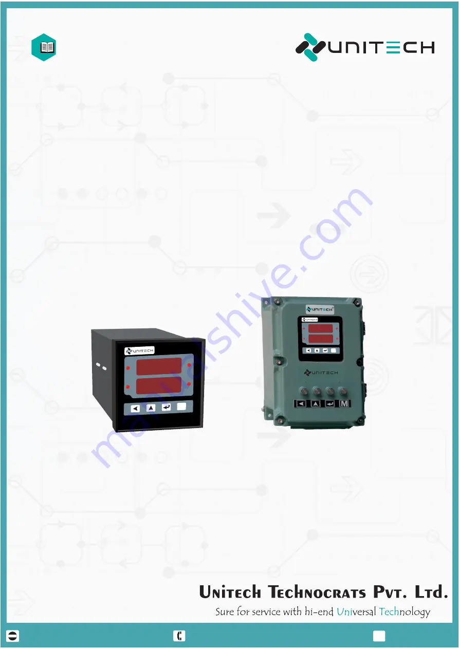
Model No. : UT-102
UNIVERSAL PROCESS INDICATOR / CONTROLLER
INSTRUCTION MANUAL
M
96 x 96
Flame Proof
UT-102
M
COM
www.utplindia.in
RL-2
RL-1
RL-4
RL-3
102.0
102.0
UT-102
M
COM
www.utplindia.in
RL-2
RL-1
RL-4
RL-3
102.0
102.0


