background image

User  Instructions

This booklet contains important information concerning the proper and safe operation of your new amplifier..
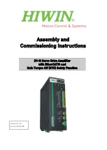
NA-Series

NA-3600 / NA-5600 / NA-8600

Made in Taiwan

Professional Power Amplif iers

Index

02  Important Precautions

 Introduction

02 


03  Front Panel

04  Rear Panel

06  Set Up

08  Operating Modes

12  Protection

13  Features

14  Specifications

UNiK A

STEREO

BRIDGE

PARALLEL

SIGNAL

SIGNAL

CLIP

CLIP

0

10

0

10

POWER

OFF

ON

MP-600

PROFESSIONAL AMPLIFIER

STEREO

BRIDGE

PARALLEL

SIGNAL

SIGNAL

CLIP

CLIP

0

10

0

10

LIMITER

LIMITER

POWER

OFF

ON

MP-1100

PROFESSIONAL  AMPLIFIER

STEREO

BRIDGE

PARALLEL

SIGNAL

SIGNAL

CLIP

CLIP

0

10

0

10

LIMITER

LIMITER

POWER

OFF

ON

MP-1600

PROFESSIONAL  AMPLIFIER

CHANNEL 1

CHANNEL 2

CHANNEL 1

CHANNEL 2

CHANNEL 1

CHANNEL 2

Clip

Sig

Clip

Prot

Limiter

Prot

Sig

on

on

0

10

Channel 

2

0

10

Channel 

1

POWER

Limiter

-

20

-

10

-

5

-

5

-

10

-

20

PROFESSIONAL


 STEREO 


AMPLIFIER

TPS1100

UNiK A

NA-3600

Clip

Sig

Clip

Prot

Limiter

Prot

Sig

on

on

0

10

Channel 

2

0

10

Channel 

1

POWER

Limiter

-

20

-

10

-

5

-

5

-

10

-

20

PROFESSIONAL


 STEREO 


AMPLIFIER

TPS1100

UNiK A

NA-5600

Clip

Sig

Clip

Prot

Limiter

Prot

Sig

on

on

0

10

Channel 

2

0

10

Channel 

1

POWER

Limiter

-

20

-

10

-

5

-

5

-

10

-

20

PROFESSIONAL


 STEREO 


AMPLIFIER

TPS1100

UNiK A

NA-8600

Summary of Contents for NA-3600

Page 1: ...0 10 0 10 LIMITER LIMITER POWER OFF ON MP 1100 PROFESSIONAL AMPLIFIER STEREO BRIDGE PARALLEL SIGNAL SIGNAL CLIP CLIP 0 10 0 10 LIMITER LIMITER POWER OFF ON MP 1600 PROFESSIONAL AMPLIFIER CHANNEL 1 CHANNEL 2 CHANNEL 1 CHANNEL 2 CHANNEL 1 CHANNEL 2 Clip Sig Clip Prot Limiter Prot Sig on on 0 10 Channel 2 0 10 Channel 1 POWER Limiter 20 10 5 5 10 20 PROFESSIONAL STEREO AMPLIFIER TPS1100 UNiKA NA 3600...

Page 2: ...avertissements supplémentaries situés dans le guide Ce symbole est utilisé pour indiquer à l utilisateur qu il trouvera d importantes instructions importantes sur l utilisation et l entretien de l appareil dans la littérature accompagnant le produit Dieses Symobl soll den Anwender vor unisollierten gefährlichen Spannungen innerhalb des Gehäuses warnen die von Ausreichender Stärke sind um einen ele...

Page 3: ...as been damaged B Objects have fallen or liquid has been spilled into the unit C The appliance has been exposed to rain or water D The fixture does not appear to operate normally or exhibits a marked change in performance Congratulations and thank you for purchasing NA 3600 NA 5600 NA 8600 amplifier These amplifiers are representation of UNiKA s continuing commitment to produce the best and highes...

Page 4: ...tinuous illumination also indicates that ACL Active Clip Limiting protection circuitry is engaged 6 Protect Indicator The red Protect LED will begin to glow when the channel goes into protect mode When the channel goes into protect mode all output for that channel will turn off This is to protect any speakers connected to the channel 7 Power Indicator This blue LED will glow when mains power is ap...

Page 5: ...nput Connectors These connectors accept input signals on balanced TRS and XLR input plugs See the figure 3 for information on polarity Connectors for each channel are in parallel the unused connectors may be used for loop through connection to other amplifiers XLR pin setting Pin 3 signal Negative Pin 2 signal Positive Pin 1 Ground 17 Channel 1 Subwoofer Mode On Off Switch NA 8600 only Turns the s...

Page 6: ...ect to your speaker s input jack Red is positive signal and Black is negative signal 24 Channel 1 Output Jack 5 Way Binding Post Connect to your speaker s input jack Red is positive signal and Black is negative signal 25 Ground Lift Switch This switch is used to disconnect the internal ground signal from the amplifier chassis ground This may reduce the buzz that is caused from an electrical 50Hz 6...

Page 7: ...post outputs on the rear of the amplifier The speaker wire may be connected by bare wire directly connected usually for permanent connections banana plug or spade connector Connections are made to channel one and channel two outputs for Stereo Mode or across the red terminals of channel one and channel two for Mono Bridge Mode IMPORTANT NOTICE Although a speaker will operate with the positive and ...

Page 8: ... the caps down on the spade connector To reduce the risk of shock or damage to your amplifier be sure that the wire connected to one binding post does not come in contact with that of another MONO BRIDGE CONNECTIONS Figure 11 Mono bridge operation connections will follow the above descriptions however when operating in mono bridge operation the speaker connections will run between the two positive...

Page 9: ... on Apply an input source signal to your amplifier Use the channel one gain control to regulate your amplifier output PARALLEL MONO Parallel ties the two channel line inputs together so that they will both be driven by the same signal without the need for external jumpers or wiring Both amplifier channels will operate independently Though they carry the same signal their gain controls affect only ...

Page 10: ...her CH 1 or CH 2 input or Both inputs REAR PANEL UNiKA NA 3600 NA 5600 NA 8600 PARALLEL STEREO BRIDGE C A U T I O N WARNING TO REDUCE THE RISK OF FIRE OR ELECTRIC SHOCK DO NOT EXPOSE THIS EQUIPMENT TO RAIN OR MOISTURE CAUTION MINIMUM LOAD IMPEDANCE 2 OHM PER CHANNEL 4 OHM BRIDGE AC IN F 12A 120V 60Hz PARALLEL STEREO BRIDGE CAUTION MINIMUM LOAD IMPEDANCE 2 OHM PER CHANNEL 4 OHM BRIDGE AC IN 120V 60...

Page 11: ...ies may be adjusted from 20Hz to 200Hz Page 11 Figure 17 details a typical Stereo Subwoofer set up PARALLEL SUBWOOFER This operation is similar to the Stereo Subwoofer operation but in Parallel When running subwoofers it is usually recommended to run them in mono mode to achieve a cleaner tighter low end This operation allows you to run several subwoofers down to a minimum of 2 ohms To avoid ampli...

Page 12: ...anana jacks Important Precautions Introduction Front Panel Rear Panels Set Up Protection Features Specifications Operating Modes CH 1 Input CH 2 Input Either CH 1 or CH 2 input or Both inputs REAR PANEL UNiKA NA 3600 NA 5600 NA 8600 CAUTION MINIMUM LOAD IMPEDANCE 2 OHM PER CHANNEL 4 OHM BRIDGE AC IN 120V 60Hz FREQUENCY CH 2 CH 1 PARALLEL DIP ON 1 2 3 4 20Hz 200Hz FREQUENCY 200Hz 20Hz NORMAL NORMAL...

Page 13: ...occasional flash keep the CLIP indicator dark to avoid overheating the amplifier channel Clipping should be kept to a reasonable minimum An amplifier s peak current draw at full output power into 2 ohms is several times what the normal draw is but its various protection circuits will prevent this condition lasting more than a minute or two SHORT CIRCUIT PROTECTION The NA Series comes with built in...

Page 14: ...his will eliminate 50Hz 60Hz cycle hum that is sometimes induced when mounting several units in the same rack LOW CUT FILTER NA 5600 and NA 8600 Only The low cut filter removes extremely low frequencies from the audio signal that could cause speaker distortion or damage The DIP switches on the rear panel allows you to enable or disable the filter for each channel as well as adjust either a 50Hz or...

Page 15: ...00W 1400W 2ohms 320W 4ohms 270W 8ohms 180W Signal To Noise Ratio below rated power 20Hz to 20KHz A Weighted 471W 4 27A 110V CLASS AB Dual 2 Speed Fans 100dB 2ohms 620W 4ohms 440W 8ohms 260W 2ohms 1000W 4ohms 700W 8ohms 420W 0 775V 0 2dB 0 01 375 620W 5 36A 110V CLASS AB Dual 2 Speed Fans 100dB 1V 0 2dB 0 01 360 990W 9A 110V CLASS AB Dual 2 Speed Fans 100dB UNiKA NA 3600 NA 5600 NA 8600 Maximum RMS...

Page 16: ...Professional Power Amplifiers UNiKA ...

Reviews: