background image

No. 20D00-2-01-3 

Original instructions


  INSTRUCTION MANUAL


Oscillating Piston Dry Vacuum Pump 
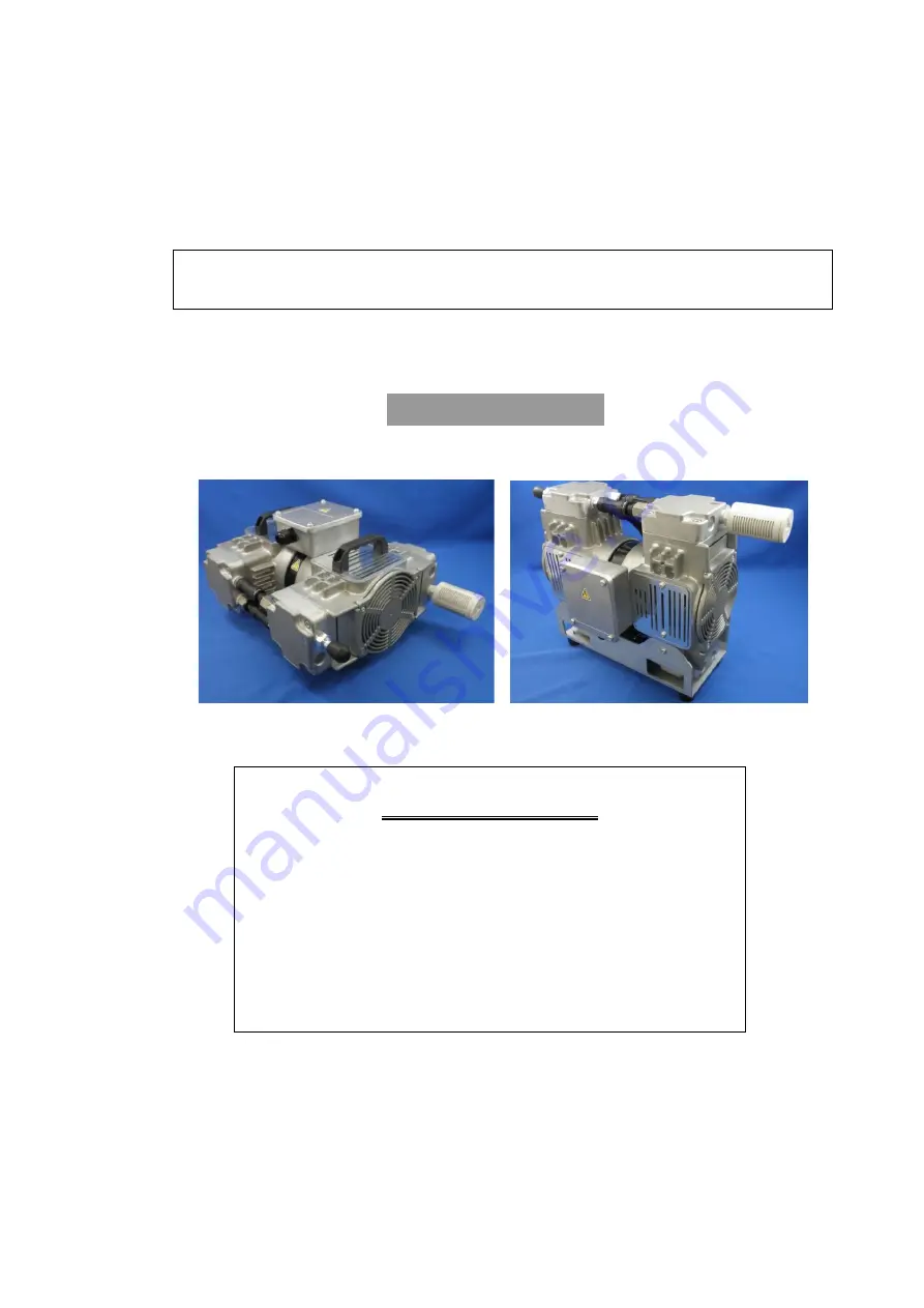
 

DOP-301SB/SVB 


Request to Users 

Please  read  this  manual  thoroughly  to  ensure  safe  and 

effective use of the equipment. 

Keep this manual in a safe place. 

Due  to  periodic  improvements  in  performance,  the 

equipment described in this manual is subject to changes 

in dimensions and specifications without prior notice.


ULVAC


KIKO, Inc. 


DOP-301SB


DOP-301SVB 

Summary of Contents for DOP-301SB

Page 1: ...sers Please read this manual thoroughly to ensure safe and effective use of the equipment Keep this manual in a safe place Due to periodic improvements in performance the equipment described in this m...

Page 2: ...2009 Compressors and vacuum pumps Safety requirements Part2 Vacuum pumps IEC EN 61010 1 2010 A1 2019 Safety requirement for electrical equipment for measurement control and laboratory use Part1 Genera...

Page 3: ...n related is in conformity with the following standards BS EN 1012 2 1996 A1 2009 Compressors and vacuum pumps Safety requirements Part2 Vacuum pumps BS IEC EN 61010 1 2010 A1 2019 Safety requirement...

Page 4: ...2 2 Dimensions 2 3 Installation and Storage 3 3 1 Cautions for Installation and Storage 3 3 2 Environmental Conditions for Installation Storage and Operation 4 3 3 Location 4 3 4 Operational Checks F...

Page 5: ...g Small Holder Plate Components 15 7 Replacing and Assembling Consumables 15 6 5 Troubleshooting List 18 7 In Conclusion 19 Warranty 19 Usage Status Check Sheet used with requests for disassembly and...

Page 6: ...t correctly Read the section on Safe Use particularly closely Keep This Manual in a Safe Place After reading this manual be sure to keep it in a safe place which is readily accessible to others needin...

Page 7: ...re any problems with the pump 1 Ensure that the tube on the side of the pump is not gripped or bent when removing the pump from the packaging Holding the pump by this tube may damage it thus reducing...

Page 8: ...of the equipment may result in death or serious injury to the operator Incorrect handling of the equipment may result in light or medium injuries to the operator or damage to the equipment Incorrect h...

Page 9: ...re or burns Power Supply 4 Always switch off the main power supply and make sure that the pump has stopped before carrying out inspection and repair 5 Ensure that the relevant wiring is in accordance...

Page 10: ...wet hands may result in electric shock 13 Touching electrical wiring etc while inserting the power cord may result in electric shock Operation 14 This pump is not designed to be explosion proof and sh...

Page 11: ...nt temperature of 40 C when connecting the pump 4 Use ventilation holes and fit a cooling fan to reduce the temperature in the vicinity of the pump Ensure that the pump cooling fan inlet is not blocke...

Page 12: ...of the pump 3 Fit an inlet filter if there is a possibility of foreign matter or dust particles entering the pump Application 4 This pump is not designed to be corrosion resistant It should only be u...

Page 13: ...containing particles dust water or corrosive gases 5 Do not operate the pump for long periods at near atmospheric pressure 1 2 Specifications Table 1 1 Product Specifications 50Hz 60Hz Model DOP 301SB...

Page 14: ...y circuit automatically to prevent burn out if the motor temperature rises due to overloading or there is a pump fault which prevents rotation 2 Always fit other protective devices eg earth leakage br...

Page 15: ...llation and Storage 3 1 Cautions for Installation and Storage See Warning 1 2 3 5 6 7 8 9 10 11 12 and 13 on p 04 and 05 See Caution 1 2 3 and 4 on p 06 See Note 1 2 and 3 on p 07 Warning Caution Note...

Page 16: ...r attention should be paid to ambient temperature when fitting the pump to equipment Use anti vibration rubbers to isolate the pump from vibrations in the equipment See 3 2 Environmental Conditions fo...

Page 17: ...eaks and fit a filter on the pump inlet 2 Use inlet piping with an internal diameter of 12 mm or more 3 Ensure that piping connected to the outlet does not cause back pressure Maximum back pressure is...

Page 18: ...ther The bearing grease and cup packing may harden under cold conditions and the pump may be difficult to start Use the following procedure in this case 1 Open the inlet to atmosphere and switch power...

Page 19: ...to drive the pump is the total of the work required to overcome the rotational resistance of the pump mechanical work and the work required to compress the air compression work and is at a maximum at...

Page 20: ...ning for procedures Request replacement by the manufacturer s service division if a repair technician is not available Consumables List Table 6 1 Consumables List DOP 301SB 301SVB Components Quantity...

Page 21: ...Inspection item Inspection details Method of inspection Every 3000 hours Backup inlet and outlet valves Abnormal wear hardening cracking Visual inspection Cup packing Abnormal wear hardening cracking...

Page 22: ...edure for Replacing Consumables in DOP 301SB 301SVB This product is comprised of four head pump chambers This description includes the procedure for replacing consumables for a single head It is recom...

Page 23: ...four M6xL30 hex headed bolts holding the head cover and remove them 2 Pull the fitting joint forwards with both hands and remove from the connecting tube Pull the left and right fitting joints altern...

Page 24: ...ate Cup Packing and Inlet Valve Rubber Separator 1 Mark the holder plate at the mark on the casing 2 Loosen the four countersunk M5xL12 screws in the holder plate While wearing gloves hold the loosene...

Page 25: ...inlet valve holder plate and inlet valve 5 Place a small amount of cleaning fluid on a soft cloth or paper and wipe the entire cylinder to remove oil and grease It is particularly important to clean t...

Page 26: ...14 6 Cylinder list a Inlet valve b Outlet valve c Backup outlet valve d Backup inlet valve...

Page 27: ...g Consumables 1 Replace the cup packing Place the cup packing on the connecting rod to ensure that the canopy is downwards 2 Insert the new inlet valve rubber separator into the groove on the rear of...

Page 28: ...e tighten the M3 L5 roundhead screw to prevent the inlet valve contacting the groove on the periphery 0 55N m 5 Place the outlet valve on the cylinder and place the backup outlet valve on the outlet v...

Page 29: ...that the replacement tube is cut to the same pump length 10 Fit the connecting tube When replacing the connecting tube ensure that the replacement tube is cut to the same pump length 11 Lay the pump...

Page 30: ...5 1 3 Vacuum gauge is unsuitable 3 Measure with a calibrated vacuum gauge suitable for the pressure range 5 1 4 The inlet piping is too small in diameter or too long 4 Connect piping of an inside dia...

Page 31: ...e and inspection etc d Malfunctions caused by modifications or repairs carried out by a party other than the manufacturer or by a service company not approved by the manufacturer e Malfunctions caused...

Page 32: ...Industrial Safety and Health Law designates particular substances as the materials to be notified 2 Usage Status Operation Method Approx hours per day years and months Continuous Operation Intermitte...

Page 33: ...6 6397 2286 ULVAC KIKO Inc https ulvac kiko com en Please contact us for products Service Base or other Inquiries from here ULVAC Inc Components Division 2500 Hagisono Chigasaki Kanagawa 253 8543 Japa...

Reviews: