background image


No

20025-2-01-5 

Original  Instructions


INSTRUCTION MANUAL


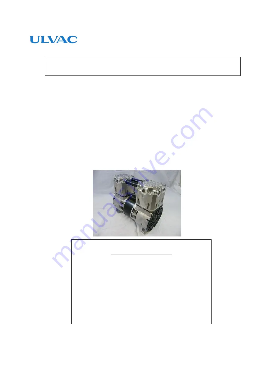
Oscillating Piston Dry Vacuum Pump 

DOP-181S series


Model 

DOP-181SA 

  DOP-181SB 

DOP-181SC 

  DOP-181SD 

DOP-181SE 


Request to Users 

Please read this manual thoroughly to ensure safe and 

effective use of the equipment. 

Keep this manual in a safe place. 

Due to periodic improvements in performance, 

the  equipment  described  in  this  manual  is  subject  to 

changes  in  dimensions  and  specifications  without  prior 

notice. 

ULVAC


KIKO, Inc.

Summary of Contents for DOP-181S Series

Page 1: ...P 181SC DOP 181SD DOP 181SE Request to Users Please read this manual thoroughly to ensure safe and effective use of the equipment Keep this manual in a safe place Due to periodic improvements in perfo...

Page 2: ...ressors and vacuum pumps Safety requirements Part2 Vacuum pumps IEC EN 61010 1 2010 A1 2019 Safety requirement for electrical equipment for measurement control and laboratory use Part1 General require...

Page 3: ...is in conformity with the following standards BS EN 1012 2 1996 A1 2009 Compressors and vacuum pumps Safety requirements Part2 Vacuum pumps BS IEC EN 61010 1 2010 A1 2019 Safety requirement for elect...

Page 4: ...Environmental Conditions for Installation Storage and Operation 4 3 3 Location 4 3 4 Operational Checks Following Installation 5 3 5 Electric connection 5 3 6 Fluctuations in the power voltage and fr...

Page 5: ...Tables Fig 2 1 DOP 181SA 181SB 2 Fig 2 2 DOP 181SC 181SD 3 Fig 2 3 DOP 181SE 3 Fig 3 1 Change region of the voltage and frequency 6 Fig 3 2 Example of Piping Used When Evacuating a Vessel 7 Fig 6 1 E...

Page 6: ...nt correctly Read the section on Safe Use particularly closely Keep This Manual in a Safe Place After reading this manual be sure to keep it in a safe place which is readily accessible to others needi...

Page 7: ...oblems with the pump 1 When take out a pump from a packing box Do not grip the pipe of the upper of the pump In addition please do not do an act bending by pushing A pipe is damaged and pump performan...

Page 8: ...the equipment may result in death or serious injury to the operator Incorrect handling of the equipment may result in light or medium injuries to the operator or damage to the equipment Incorrect han...

Page 9: ...s may decline an overhaul Please pay attention enough 4 To reduce the risk of fire and explosion damage enclose the pump by non flammable cover Power Supply 5 Always switch off the main power supply a...

Page 10: ...or objects into the motor inlet may result in electric shock injury or fire 18 Operating the pump with the discharge outlet blocked or with a device which prevents passage of gas to the discharge outl...

Page 11: ...When the thermal protector operates the pump will become extremely hot Please do not touch the pump Touching the pump in that condition will cause burn injury Turning off the main power supply of the...

Page 12: ...istics 5 This pump is only for vacuum pumping Use at near atmospheric pressures for long periods of time may result in a malfunction Operation 6 Use the pump at an ambient temperature of Ambient tempe...

Page 13: ...mpt to evacuate gases containing particles dust water or corrosive gases 5 Do not operate the pump for long periods at near atmospheric pressure 1 2 Specifications Table 1 1 Product Specifications DOP...

Page 14: ...rcuit automatically to prevent burn out if the motor temperature rises due to overloading or there is a pump fault which prevents rotation 2 Always fit other protective devices eg earth leakage breake...

Page 15: ...Fig 2 2 DOP 181SC 181SD Fig 2 3 DOP 181SE...

Page 16: ...ve gas f Not subject to direct sunlight g No danger of fire h Do not exceed the maximum ambient temperature of the temperature range of product specification at the time of pump installation refer to...

Page 17: ...r higher one earth wire included 3 Phase motor 4 Core cable Size of the wire lead 1 0m or larger 300V or more 10A or more 80 or higher one earth wire included The temperature rating of the power cord...

Page 18: ...lting in the grade which shortens a life remarkably and the characteristic a temperature rise etc do not apply correspondingly in the state of rating Moreover main rating shows rated torque N m 3 7 Th...

Page 19: ...ge pressure 4 In case of selecting the inlet pipe and exhaust pipe that are not from our products please select the exhaust pipe that has same or larger inner diameter length with the inlet pipe 5 Ple...

Page 20: ...5 6 and 9 on p 06 Immediately switch off the main power and contact to the manufacturer when thermal protector is activated 4 3 Starting in Cold Weather The bearing grease and cup packing may harden u...

Page 21: ...value achieved with dry air 5 3 Power Requirements The power required to operate the pump is the total of the work required to overcome the rotational resistance of the pump mechanical work and the wo...

Page 22: ...SUS 6000 Hr O ring 4 EPDM 6000 Hr Head gasket 2 EPDM 6000 Hr Bearing 1 set 15000 Hr Power supply cord 1 set At any time Life of these components tends to be extended when the requirements in 4 1 Cauti...

Page 23: ...ediately after operation After stopping the pump leave it for 30 minutes or more and begin replacing consumables and cleaning only after checking that it has cooled sufficiently 2 To prevent ingestion...

Page 24: ...pump Refer to the exploded view Fig 6 1 Remove all cap screws M6 95L 8 No 1 that fasten the pump head No 2 to the Casing Remove the pump heads assembly No 5 Head gasket No 6 is attached inside the pum...

Page 25: ...e a new O rings Clean a connecting pipe s O ring groove installation hole before replace The head gasket gets pinched when extruding from the gasket groove Ensure that head gasket are fully assembled...

Page 26: ...rts Photo7 Cylinder Gasket Photo8 Cup packing Connecting rod 6 4 7 Reassembling the pump Refer to the exploded view Fig 6 1 clause 6 4 2 Disassembling the pump Place the cup packing cup packing retain...

Page 27: ...Fig 6 1 Exploded view OUTLET INLET...

Page 28: ...2 Measure the pressure correctly 5 1 3 Vacuum gauge is unsuitable 3 Measure with a calibrated vacuum gauge suitable for the pressure range 5 1 4 The inlet piping is too small in diameter or too long...

Page 29: ...ons maintenance and inspection etc d Malfunctions caused by modifications or repairs carried out by a party other than the manufacturer or by a service company not approved by the manufacturer e Malfu...

Page 30: ...Industrial Safety and Health Law designates particular substances as the materials to be notified 2 Usage Status Operation Method Approx hours per day years and months Continuous Operation Intermitte...

Page 31: ...6 6397 2286 ULVAC KIKO Inc https ulvac kiko com en Please contact us for products Service Base or other Inquiries from here ULVAC Inc Components Division 2500 Hagisono Chigasaki Kanagawa 253 8543 Japa...

Reviews: