background image

Cont ...

INSTALLATION INSTRUCTIONS
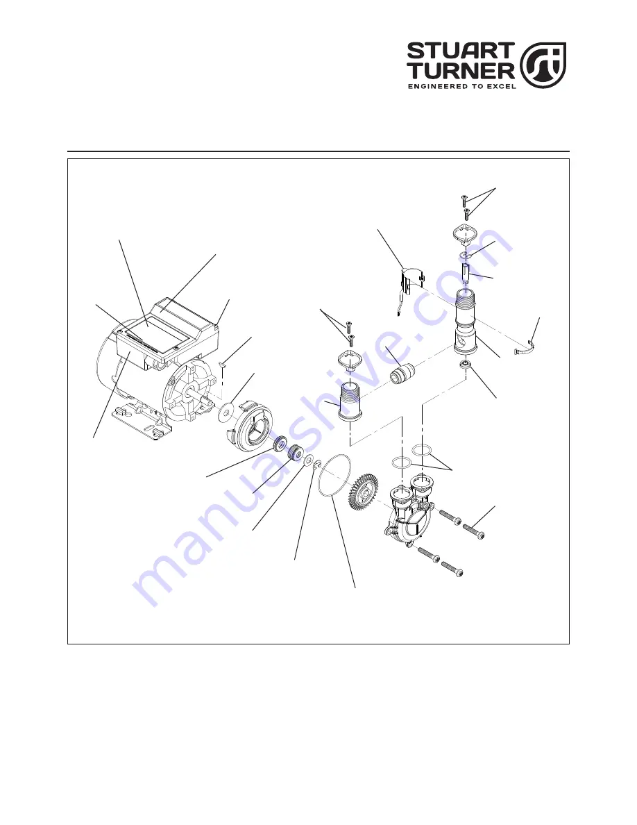
SERVICE KIT  - 

FLOMATE, MBF 12 (Pre-November 2017) Part No.


28457

Note:  1)  Items 16, 23, 24 are pre-assemble parts, see relevant section for detailed instructions.
 

2)  See relevant section for detailed instructions.

Fig. 1

20 (Section 3)
Capacitor (not shown)

17 (Section 5)
PCB
(not shown)

19 (Section 3 & 5)
Adhesive foam pad
(not shown)

1 (Section 1)
Woodruff key

7 (Section 1)
‘O’-ring (ID 66.4)

5 (Section 1)
Washer (OD ¾)

8 (Section 1)
Screws M6 x 35 mm

6 (Section 1)
Circlip

4 (Section 1)
Rotary seal

3 (Section 1)
Seal 
counterface

18 (Section 4)
Strainer relief bush 
(not shown)

21 (Section 4)
Reed switch

12 (Section 2)
Screws (M4 x 16 mm)

16 (Section 2)
Non return 
valve assembly

13 (Section 2 & 4)
Reed switch tie wrap

10 (Section 2)
Clip

11 (Section 2)
Magnetic float

14 (Section 2)
Flow regulator

15 (Section 2)
‘O’-ring (ID 24.6)

12

23 (Section 2)
Inlet assembly

2 (Section 1)
Thrower

22 (Sections 3, 4 & 5)
Screws (K40 x 16 mm)

24 (Section 2)
Outlet assembly

Summary of Contents for 28457

Page 1: ...odruff key 7 Section 1 O ring ID 66 4 5 Section 1 Washer OD 8 Section 1 Screws M6 x 35 mm 6 Section 1 Circlip 4 Section 1 Rotary seal 3 Section 1 Seal counterface 18 Section 4 Strainer relief bush not shown 21 Section 4 Reed switch 12 Section 2 Screws M4 x 16 mm 16 Section 2 Non return valve assembly 13 Section 2 4 Reed switch tie wrap 10 Section 2 Clip 11 Section 2 Magnetic float 14 Section 2 Flo...

Page 2: ...O ring ID 66 40 c sec 1 78 1 19 Adhesive Foam Pad not shown 1 8 Screws M6 x 35 mm 4 20 Capacitor not shown 1 9 Seal Applicator Tool not shown 1 21 Reed Switch 1 10 Clip 1 22 Screws K40 x 16 mm 4 11 Magnetic Float 1 23 Inlet Assembly 1 12 Screws M4 x 16 4 24 Outlet Assembly 1 Check to see that you have all the above items and that they are not damaged If any damage is found contact Stuart Turner Lt...

Page 3: ...ch pump part must be removed noting its exact position and sequence Difficulties may be experienced in the removal of the impeller To overcome this 2 screwdrivers can be used to prize the impeller from the shaft as shown ensuring equal pressure is applied to each side of the impeller to avoid shaft bending 4 Clean all the components not replaced by the service kit SEAL IDENTIFICATION The seal as s...

Page 4: ... seal assembly item B onto the motor shaft until it is flat against the seal seat Fig 5 The shaft may be lubricated with clean water to assist assembly Assemble the spring and location plate onto the shaft so as to complete the rotary seal assembly Fig 6 3 The washer item C can then be placed on the shaft and the whole assembly held into position by locating the E clip item D in the groove and pus...

Page 5: ...sembly 1 14 Flow Regulator 12 l min 1 23 24 O ring ID 13 c sec 3 mm 2 15 O ring ID 24 60 c sec 2 40 2 Parts pre assembled DISASSEMBLY Reference Fig 1 Remove the existing reed switch by cutting the securing tie wrap Item 13 Remove four screws Item 12 and carefully remove manifold assembly from pump Carefully dismantle the outlet assembly Item 24 inlet assembly Item 23 NRV assembly Item 16 and manif...

Page 6: ...egulator item 14 is fitted during this operation as NOT to do so will infringe Regulation 5 of the Water Supply Regulations that states any pump fitted to the mains supply pipe can only draw 12 l min or less Note Ensure the manifold clamps item A are placed over the outlet assembly Item 24 and inlet port Item 23 BEFORE assembling them onto the NRV assembly item 16 see Fig 10 Note For the correct o...

Page 7: ...e as highlighted X X in Fig 14 below and feed the tie wrap through the second catch The tie wrap can now be pulled tight to secure the reed and the excess cut to length as shown in Fig 15 INITIAL OPERATING INSTRUCTIONS Do not run pump dry Allow the liquid to be pumped to enter the pump body thus ensuring the seal is lubricated before switching the pump on Failure to do this will damage the seal Ca...

Page 8: ...ectrical standard EN 60335 1 It is essential that prior to any disturbance of this internal wiring all cable routing and securing details are carefully noted to ensure reassembly to the same factory pattern is always maintained Reference Fig 16 Remove 4 screws item 22 and carefully remove terminal box lid IMPORTANT Take note of capacitor wiring connection and colours before removal Disconnect and ...

Page 9: ... the linked capacitor terminals as shown INITIAL OPERATING INSTRUCTIONS Consult instruction manual for commissiong instructions Do not run pump dry Allow the water to be pumped to enter the pump body thus ensuring the seal is lubricated before switching the pump on Failure to do this will damage the seal Carefully check pump and pipework for leaks whilst pump running and stationary before leaving ...

Page 10: ...eassembly to the same factory pattern is always maintained Remove four screws and carefully remove terminal box lid item 22 Note the cable routing within the terminal box Fig 19 Slacken the two screws retaining the reed switch wires on the PCB Remove the strain relief bush and reed switch cable by gripping with pliers Fig 20 and pulling downwards from the terminal box Remove the existing reed swit...

Page 11: ...reed switch wires to the PCB Fig 19 For correct operation of the flow switch the reed must be secured to the body Fig 22 Firstly feed the tie wrap item 13 through the retainer on the reed switch ensuring that the tie wrap serrations are facing outwards Fig 21 Locate the reed switch within the body groove as highlighted X X Fig 22 and feed the tie wrap through the second catch The tie wrap can now ...

Page 12: ...n pump dry Allow the water to be pumped to enter the pump body thus ensuring the seal is lubricated before switching the pump on Failure to do this will damage the seal Carefully check pump and pipework for leaks whilst pump running and stationary before leaving the installation unattended X X Fig 22 Fig 23 ...

Page 13: ...cured to ensure compliance with the electrical standard EN 60335 1 It is essential that prior to any disturbance of this internal wiring all cable routing and securing details are carefully noted to ensure reassembly to the same factory pattern is always maintained Fig 24 MAIN WINDING THERMOTRIP CAPACITOR START WINDING FLOWSWITCH REED S3 BLUE BROWN BLACK GREEN YELLOW BLUE BROWN L M N N S3 S3 L E N...

Page 14: ...ve two M4 nuts item A and carefully lift PCB Item 17 away from terminal box Damaged components must be replaced Contact Stuart Turner for advice on replacements not supplied with kit REASSEMBLY Reassembly is the reverse of the disassembly instructions with the new replacement parts fitted as required Note For correct installation the capacitor must be secured and positioned as detailed in Figs 26 ...

Page 15: ...switching the pump on Failure to do this will damage the seal Carefully check pump and pipework for leaks whilst pump running and stationary before leaving the installation unattended Stuart Turner Limited reserves the right to amend specifications without notice Receptacles at 45o approximately 19 Fig 26 Fig 27 Receptacles at 45o approximately Receptacles at 45o approximately Blue wires Black wir...

Page 16: ...Stuart Turner Ltd Henley on Thames Oxfordshire RG9 2AD ENGLAND Tel 44 0 1491 572655 Fax 44 0 1491 573704 info stpumps co uk www stuart turner co uk Issue No 4817 1 02 Pt No 20003 ...

Reviews: