Ultra Pure SYSTEMS pureMist, Engineering Manual
The Ultra Pure SYSTEMS pureMist is a cutting-edge engineering manual providing detailed instructions on how to optimize your system for maximum performance. Download the manual for free from manualshive.com and enhance your understanding of this innovative product. Elevate your knowledge with the pureMist manual today.
Share
Download


Reviews:
No comments
Related manuals for pureMist

CS3
Brand: Made Pages: 8

SONZAI Series
Brand: Toyotomi Pages: 68

7031-033
Brand: AXXIOM Manufacturing, Inc. Pages: 58

HG 5-10
Brand: Deltech Pages: 8

CH-D008WDP6-20LD
Brand: Cooper & Hunter Pages: 60

VAPOR OUT SDHM-16L
Brand: Singer Pages: 68

MI-AH001
Brand: Miroco Pages: 10

DH20
Brand: Duronic Pages: 97

Platinum GPDH260
Brand: Goldair Pages: 8

UA HD3 Series
Brand: Carel Pages: 34

MJ-EZ6CX-S1-IT
Brand: Mitsubishi Pages: 50

KT Series
Brand: Elsteam Pages: 40

AIR FRESH
Brand: Soehnle Pages: 57

DHF22CEL
Brand: TESY Pages: 38

DH 305
Brand: Orbegozo Pages: 21
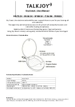
Dry-Smart
Brand: TALKJOY Pages: 6

LAF 31
Brand: VEAB Heat Tech Pages: 36

Aura QS
Brand: Desert Aire Pages: 94


