U-Line UOCL115, User Manual & Service Manual
The U-Line UOCL115 is an exceptional product designed to enhance your kitchen experience. With its sleek design and advanced features, this appliance is a must-have for any modern home. Ensure optimal performance by downloading the comprehensive User Manual & Service Manual for free at manualshive.com.
Share
Download


Reviews:
No comments
Related manuals for UOCL115

Nanopresso
Brand: wacaco Pages: 7

PRO ES1500 Vero Barista
Brand: Waring Pages: 2

Pane Express Top 131
Brand: ARIETE Pages: 206
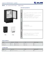
U-BI95B-00A
Brand: U-Line Pages: 2

Ice Undercounter Series Cubers ICEU070A
Brand: Ice-O-Matic Pages: 21

WM 40423
Brand: Kalorik Pages: 28
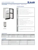
CLR1215SOD
Brand: U-Line Pages: 2

CO-O4
Brand: Cime Pages: 32

S27
Brand: Caffitaly System Pages: 64

PTC-PRII
Brand: Prowill Pages: 4

AROMATICA U27.51
Brand: Rotel Pages: 73

ES-124775
Brand: emerio Pages: 60

Moltio HD8768 AMF
Brand: Saeco Pages: 3

GE-2406T Series
Brand: Gainscha Pages: 33

LPSGEV02
Brand: La Pavoni Pages: 178

PC5510
Brand: Concept2 Pages: 71

49976
Brand: Hamilton Beach Pages: 11

Micro Cube M 120
Brand: Wessamat Pages: 58


