U-Line Marine Series WH95FC, User Manual
The U-Line Marine Series WH95FC refrigerator is a top choice for boaters and marine enthusiasts. For easy setup and maintenance, be sure to download the free User Manual from our website. The manual provides step-by-step instructions for optimal performance and efficiency. Get your copy today!
Share
Download


Reviews:
No comments
Related manuals for Marine Series WH95FC

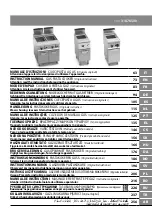
MASTER
Brand: ZAGGIA Pages: 18
31876500
Brand: GGMgastro Pages: 257

F073-C201
Brand: Hoshizaki Pages: 43
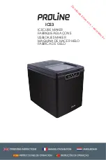
ICE3
Brand: Proline Pages: 40

GEM Series
Brand: Ice-O-Matic Pages: 29

BBME0015
Brand: Wolfgang Puck Pages: 18

Supremo XSL
Brand: V-ZUG Pages: 52

711714009
Brand: Saeco Pages: 46

LD630T
Brand: Oki Pages: 250

FP10032US
Brand: Costway Pages: 12

AquaCafe
Brand: MTN Products Pages: 3
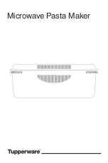
10049020724
Brand: Tupperware Pages: 47

ALS/XLS 204
Brand: Novexx Solutions Pages: 312

1 GR VP
Brand: B.F.C. Pages: 32

OKKA OK001
Brand: Arzum Pages: 76

Kit IM-5SS
Brand: GE Pages: 72

Ek'Oh
Brand: Malongo Pages: 84

GEM-120A
Brand: Curtiss Pages: 12


