


Reviews:
No comments
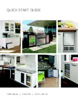
Related manuals for BI1215 1000 Series

Incanto HD8917
Brand: Saeco Pages: 80

CLASSE 10
Brand: Rancilio Pages: 2

Odea Giro Plus
Brand: Saeco Pages: 2
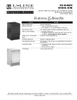
Origins BI-98
Brand: U-Line Pages: 2
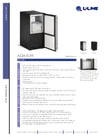
ADA151M
Brand: U-Line Pages: 2

CLR1215
Brand: U-Line Pages: 53
CLR1215
Brand: U-Line Pages: 17

Pane Express Top 131
Brand: ARIETE Pages: 206

0827974
Brand: Rowenta Pages: 98

10002928
Brand: Saeco Pages: 68

Triple Scoop KP300
Brand: Euro-Pro Pages: 16

Azzurri Classico CM631
Brand: Blue Ice Pages: 96

Vostok 1
Brand: M&V S.r.l. Pages: 14

KM740
Brand: T-Fal Pages: 54

ROMA TCS SED
Brand: Sanremo Pages: 155

Tharo V-424 Plus
Brand: Tharo Systems Pages: 32

DW - 80
Brand: Cofman Pages: 18

ZESPRESSO TT-CM23
Brand: TurboTronic Pages: 16


