u-blox C101-D9S, User Manual
The u-blox C101-D9S is a cutting-edge device that offers exceptional performance. To maximize its potential, we provide a comprehensive and detailed User Manual, available for free download at manualshive.com. This manual will effortlessly guide you through the setup and operation of the product, ensuring you unlock its full functionality.
Share
Download


Reviews:
No comments
Related manuals for C101-D9S
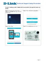
DCS-5000L
Brand: D-Link Pages: 3
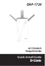
DAP-1720
Brand: D-Link Pages: 24

PTP 820 Series
Brand: Cambium Networks Pages: 3

PTP 820G
Brand: Cambium Networks Pages: 68

Ripwave
Brand: Navini Networks Pages: 8

AT-MWS600AP
Brand: Allied Telesis Pages: 2

BulletM2-HP
Brand: Ubiquiti Pages: 12

BN-T10
Brand: Bonein Pages: 6

UniFi UAP-AC-LITE
Brand: Ubiquiti Pages: 28

EA6700
Brand: Linksys Pages: 124

WR254
Brand: Abocom Pages: 1

AWK-4131
Brand: Moxa Technologies Pages: 17

AWK-3121B Series
Brand: Moxa Technologies Pages: 14

EOA3630
Brand: EnGenius Pages: 58

ENH700EXT
Brand: EnGenius Pages: 67

EAP1750H
Brand: EnGenius Pages: 64

KB3050
Brand: Kingbird Pages: 9

TCSK-01
Brand: TCS Pages: 16


