Satellite Camera installation (continued)
Note:
To be fully EMC/EMI compliant the installer/user must clip the provided
ferrites onto the Satellite Camera & Building cables after they have been
passed through the conduit hole in the ICU enclosure box, the distance from
the boot of the RJ45 connector is approximately 6 Inches (155mm) to allow a
loop inside the box and the ferrites to sit freely
alongside the PCB’s.
Hardware setup
To set up your Illustra Insight hardware, complete the following steps:
1.
Connect the Satellite Camera Module through its connector (F) (Figure 2)
to the Satellite Camera Connector (D) (Figure 1) on the ICU with the 10m
S/FTP CAT6 cable provided.
Note:
To ensure the correct operation of the camera, alternative S/FTP
CAT6 cables should not be used.
2.
Connect the Illustra Control Unit to an IEEE 802.3bt power source (
A
).
3.
Optional:
Connect a Wiegand Interface (
C
) or OSDP Interface (
B
) for
Access Control Integration.
Network Configuration
To configure your Illustra Insight Camera network, complete the following steps:
1.
Access the camera web GUI using
http://<ipaddress
>
2.
From the
View
selection, select
Setup.
3.
Select
Network
from the
Setup
menu and configure the network
parameters as required.
Note:
It is not possible to configure a Primary DNS Server so leave this
blank.
4.
Click
Apply
to apply the new network settings.
Note:
The camera then reboots.
Security
Quick Start Guide
(8200-1923-01_A0)
Illustra Insight 2MP Facial Recognition Access Control Camera
In the box
1 x Illustra control unit
1 x Satellite camera module
1 x Quick Start Guide
1 x Torx bit
1 x Drill template
1 x 10m S/FTP CAT6 cable (Do
not
modify the cable)
2 x Cable clamp ferrites
Installation tools
1 x Drill
Quick reference
Default IP: 192.168.1.168 (DHCP enabled)
Default Username: admin
Default Password: admin
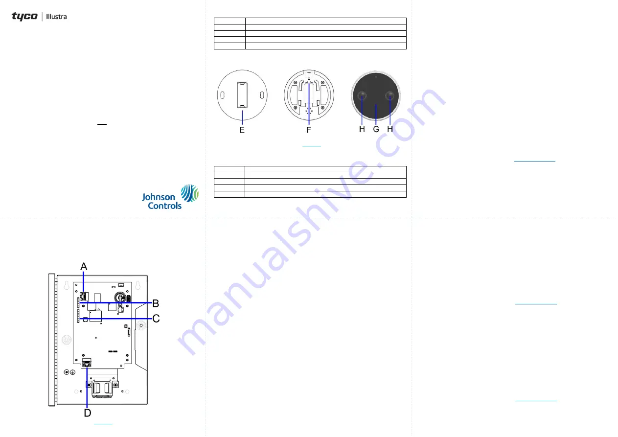
Figure 1: Illustra control unit parts
Figure 1
Table 1: Illustra control unit parts descriptions
Part
Description
A
Power Over Ethernet IEEE 802.3bt Network Connector
B
OSDP Interface
C
Wiegand Interface
D
Satellite camera connector
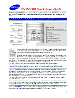
Figure 2: Illustra Insight camera parts
Figure 2
Table 2: Illustra Insight camera parts descriptions
Part
Description
E
Wall Mounting Bracket
F
Location of the Satellite cable connection
G
Satellite camera module
H
Lenses
Required items not included in the box (Camera 1 to the Server)
1 x Single port IEEE 802.3bt Injector (e.g. PoE60U-1BT).
1 x Ethernet cable CAT5/6 from Injector output to the Illustra Control Unit.
1 x Ethernet cable CAT5/6 from Injector input to Facial Recognition Server
Ethernet port.
Required items not included in the box (Additional number of cameras to the
Server)
‘N’ x Single port IEEE 802.3bt Injector (e.g. PoE60U-1BT).
1 x Port Gigabit Ethernet Switch.
‘N’ x Ethernet cable CAT5/6 from Injector output to the Illustra Control Unit.
‘N’ x Ethernet cable CAT5/6 from Injector input to Network Switch.
1 x Ethernet cable CAT5/6 from Network Switch to Facial Recognition Server
Ethernet port.
Satellite Camera installation
To attach the satellite camera to a surface, complete the following steps:
1.
Place the mounting template on the surface at the recommended height
of 62’’ (5.2 foot / 1.6m / 1575mm) and drill holes that correspond to those
identified on the template for mounting and cable tray purposes.
2.
Place the mounting bracket onto the surface and align the holes on the
mounting bracket with the holes on the surface and ensure that the
bracket is level and the screws in place.
Note:
The camera end of the CAT6 S/FTP cable in the wall should be
passed through the bracket mounted on the wall and be plugged into the
back of the satellite camera module (F) (Figure 2).
3.
Place the camera onto the mounting bracket and set at it at the desired
angle +/- 20 degrees and use the Torx bit provided to tighten the security
screw located at the top of the mounting bracket to securely attach and
lock the camera to the mounting bracket.
Streaming live video
The Illustra Insight Camera supports RTSP streaming of H.264 encoded live
video. To use this feature, a video streaming client can be used. To access the
live video, use the following URL:
rtsp://<ipaddress>/live_video
Note
: The <ipaddress> is the IP address of the Illustra Insight Camera.
Capturing a raw snapshot
After you configure your camera settings, you can capture a raw snapshot in UYVY
format.
1.
Access the camera web GUI using
http://<ipaddress
>
2.
From the
View
selection, select
Setup.
3.
Select
System
from the
Setup
menu and then select
Raw Snapshot
.
4.
Click the
Download
button to capture a snapshot. The snapshot is
automatically downloaded in approximately 3 seconds.
Access control system interface
Option 1: Wiegand
The Control Unit implements a standard Wiegand Interface to interface to an
Access Control System. By default, the camera is configured to output a MIFARE
32-bit compatible signal to communicate a card number via Wiegand. To configure
the Wiegand interface, complete the following steps:
1.
Connect a standard Wiegand interface cable to the Wiegand Interface (
C
)
Note:
The hardware and firmware use the D0/D1 and RED, YELLOW,
GREEN signals.
2.
Access the camera web GUI using
http://<ipaddress
>
3.
From the
View
selection, select
Setup.
4.
Select
Frictionless Access
from the Setup menu and then select
Test.
5.
Enter an example card number as a base 10 integer (e.g. 65005).
6.
Click the
Send button
to send the card ID through Wiegand.