


M-D Pneumatics
®
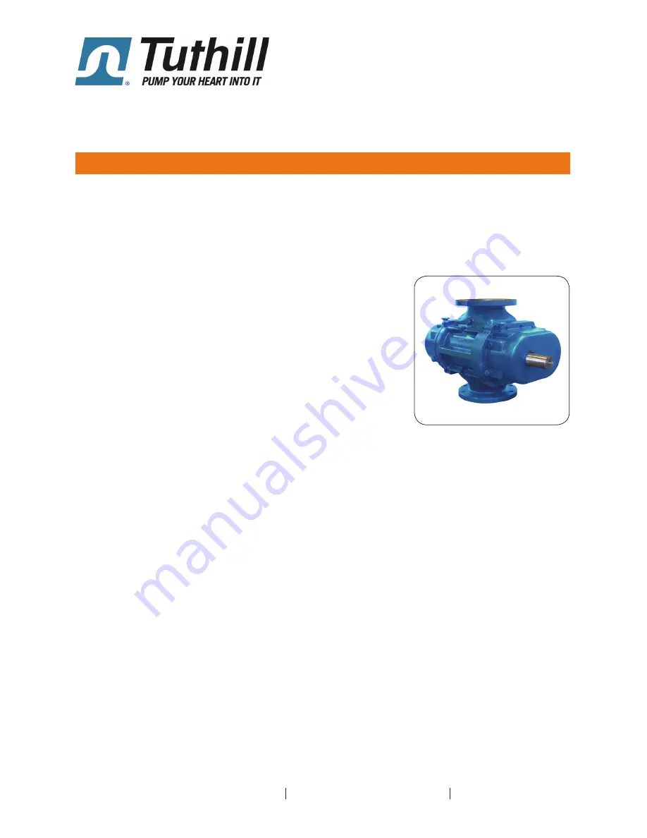
Rotary Positive Displacement Blower
Qx
Models
3200
4600
6000
OPERATOR’S MANUAL
Manual 2010 Rev B p/n 2010
Tuthill Vacuum & Blower Systems tuthillvacuumblower.com 800.825.6937
WARNING: Do Not Operate Before Reading Manual
Operator
’s Manual: T
uthill Qx Rotary Positive Displacement Blower
Copyright © 2019 Tuthill Vacuum & Blower Systems
All rights reserved. Product information and specifications subject to change.
Summary of Contents for 3200
Page 39: ......


