Trotec TTK 105 S HC, Operation Manual
The Trotec TTK 105 S HC is a powerful and efficient dehumidifier designed for both home and commercial use. To ensure smooth operation, make sure to read and follow the detailed instructions provided in the free Operation Manual. Download your manual for free from our website to maximize the performance of your Trotec dehumidifier today.
Share
Download


Reviews:
No comments
Related manuals for TTK 105 S HC

LIMPIA 6
Brand: Olimpia splendid Pages: 52

87795024
Brand: Uberhaus Pages: 22

35208
Brand: Hunter Pages: 2

5412810405831
Brand: nedis Pages: 44

Calorex DH75 Series
Brand: Dantherm Pages: 19

TDH-22
Brand: Turbo Pages: 24

DSC-90ES
Brand: Wood’s Pages: 25

HD60002
Brand: Emerson Pages: 12

MoistAIR HD1405
Brand: Emerson Pages: 16

MoistAIR HD1205
Brand: Emerson Pages: 16

MoistAir MA 1200
Brand: Emerson Pages: 20

HD13002
Brand: Emerson Pages: 16
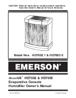
HD7002-1
Brand: Emerson Pages: 16

MA0800
Brand: Emerson Pages: 16

MA1200-1
Brand: Emerson Pages: 19

CA-601
Brand: Clean Air Pages: 9

Huey
Brand: Vornadobaby Pages: 88

EHUMD800ASM00BA
Brand: CAC / BDP Pages: 19


