

Transition
Networks
SESPM1040
‐
541
‐
LT
‐
xx
Quick
Start
Guide
33783
Rev.
A
https://www.transition.com
Page
1
of
2
SESPM1040
‐
541
‐
LT
‐
xx
Self
‐
Enclosed
Managed
Hardened
Gigabit
Ethernet
PoE++
Switch
Quick
Start
Guide
See
the
Install
Guide
for
important
Cautions,
Warnings
and
Safety
information.
See
the
SESPM1040
‐
541
‐
LT
‐
xx
webpage
for
the
latest
firmware,
etc.
Package
Contents
:
Verify
you
received:
One
SESPM1040
‐
541
‐
LT
‐
xx
Switch,
one
Documentation
Postcard,
one
printed
Quick
Start
Guide,
and
hole
plugs
in
a
bag.
You
can
configure
the
switch
directly
in
the
box
and
unpack
at
the
install
location.
Tools
and
Equipment
:
One
or
two
stud
size
6
ring
terminals
to
use
as
protective
ground
connector
(
‐
DC
or
‐
PD
version;
‐
AC
is
already
grounded).
A
crimping
tool.
12–18
gauge
copper
ground
wire
(or
as
appropriate).
Wire
‐
stripping
tools
to
strip
12–18
gauge
wires.
#
‐
2
Phillips
screwdriver.
Flat
‐
blade
screwdriver.
Torque
Driver.
3/8"
nut
driver
to
lock
and
unlock
enclosure.
Wire
Gland
tool
for
loosening/tightening.
Wall
Mount
Installation
:
1.
Place
switch
at
desired
location
and
secure
with
mounting
screws
(not
included).
2.
Ground
the
switch
before
connecting
other
cables.
3.
Disconnect
grounding
only
after
disconnecting
all
other
cables.
Pole
Mount
Installation
:
Use
optional
Pole
Mount
Bracket
Kit
and
follow
kit
instructions.
Mounting
straps
or
U
‐
bolts
are
needed
(not
provided).
Wire
Gland
Plug
Kit
:
Various
wire
gland
inserts
are
provided.
To
maintain
NEMA/IP
rating,
use
the
most
appropriate
size
for
your
cable
and
fill
unused
holes
with
hole
plugs
provided.
Cabling
Procedure
:
For
standard
installs,
plug
the
AC
power
cord
into
an
outdoor
‐
rated
receptacle.
To
hardwire
the
switch,
perform
these
steps:
1.
Connect
cable
glands
or
¾
NPT
conduit
connectors
to
the
face
of
the
switch.
Ensure
that
connectors
are
fully
waterproof.
2.
Thread
outdoor
rated
waterproof
AC
cable
(must
comply
with
all
local,
national
and
country
electrical
codes)
from
source
thru
piping/gland
to
the
terminal
block.
3.
Pair
and
secure
ground,
line,
and
neutral
to
the
appropriate
positions
on
the
three
pin
terminal
block
and
reattach
the
protective
covering.
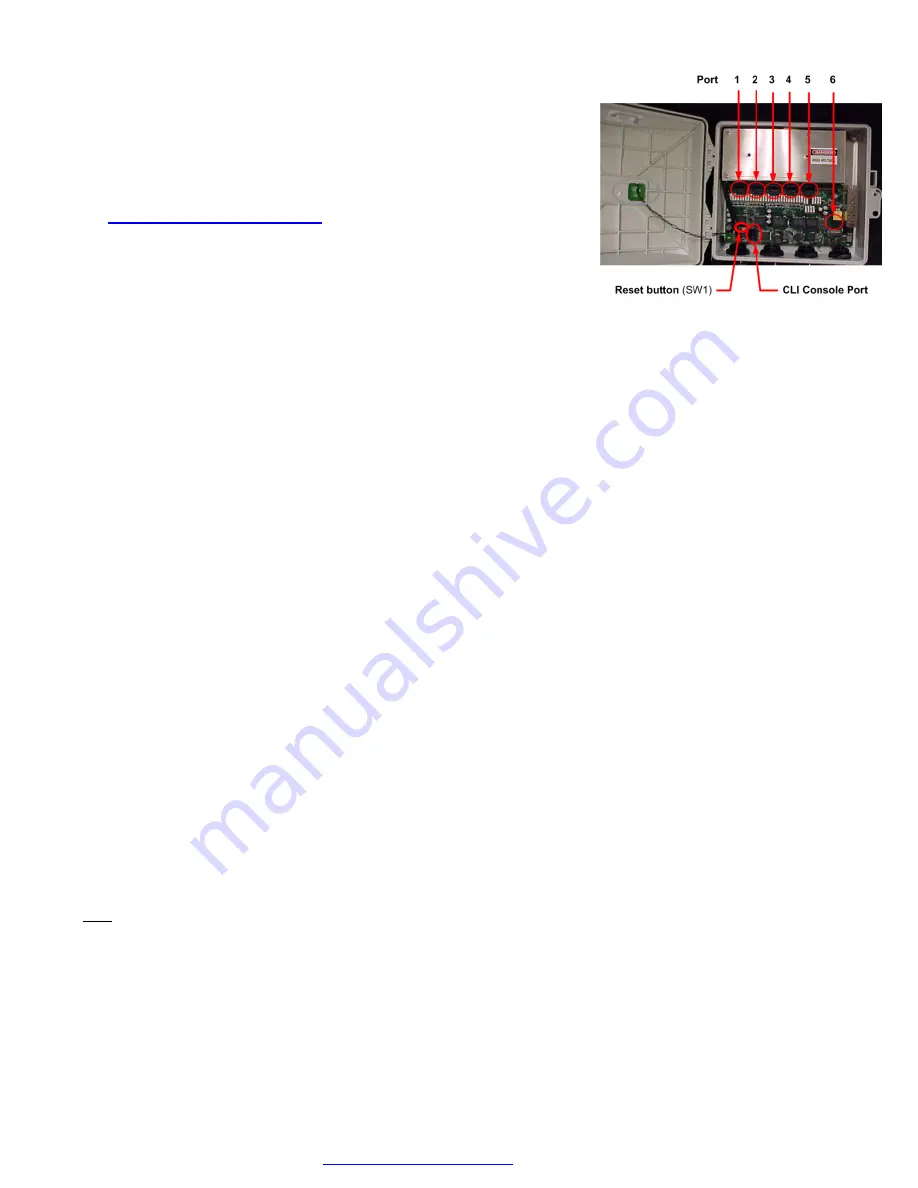
Port
Configuration
:
Ports
1
‐
4
are
10/100/1000Base
‐
T
PoE++
PSE
Ports.
Port
5
is
a
combo
10/100/1000Base
‐
T
or
a
100/1000Base
‐
X
uplink
port.
On
the
‐
AC
and
‐
DC,
Port
5
can
either
be
used
as
a
copper
or
fiber
port.
On
the
‐
PD
version,
Port
5
is
normally
used
for
PoE
power
input;
the
SFP
option
is
not
available
unless
using
fiber
cable
running
in
parallel
to
a
copper
cable
as
the
power
input,
then
port
5
can
be
used
as
a
fiber
port
(or
copper)
instead
of
using
it
exclusively
as
the
PoE
power
input
port.
Port
6
is
available
when
you
add
the
optional
Additional
Combo
Port
Module
or
optional
Wireless
Extension
Module.
Note
:
If
using
more
than
one
90W
port,
alternate
ports,
use
ports
1
and
3,
or
ports
1
and
4,
or
ports
2
and
4.
Exception:
ports
2
and
3
are
allowed.
Console
Port
:
The
Console
port
provides
an
RJ45
connector
for
serial
connection
to
a
network
PC
running
a
terminal
emulation
package
such
as
HyperTerm
or
PuTTY.
See
the
Operation
Guide.
SFP
Installation
:
The
bottom
SFP
cage
is
for
the
included
combo
port;
the
top
SFP
cage
is
for
the
optional
2
nd
combo
port.
On
the
bottom
SFP
cage
insert
the
SFP
with
the
label
down.
On
the
top
SFP
cage
insert
the
SFP
with
the
label
up.
Use
only
Industrial
SFPs
for
outdoor
switch
installation.
Factory
Reset
button
:
Located
in
the
lower
left
corner
of
the
switch
PCB.
Press
less
than
10
seconds
to
issue
a
power
down
(system)
reset.
Press
more
than
10
seconds
to
reset
to
factory
defaults.
Configuration
Procedures
:
You
can
configure
the
switch
using
NFC
(easiest
way),
Web
UI,
or
CLI.
NFC
requires
a
tablet
or
smart
phone
with
Android
OS
and
NFC
capability.
Web
UI
requires
current
Windows
or
Linux
distro
and
a
current
web
browser.
CLI
access
is
via
a
Telnet
session
or
a
PC
running
a
terminal
emulation
package.


