Trane RTUD, Installation Operation & Maintenance
The Trane RTUD is a powerful unit designed for heating, cooling, and ventilation. This user-friendly product comes with a comprehensive Installation Operation & Maintenance manual available for free download on our website. Stay informed and keep your unit running smoothly by accessing the manual from manualshive.com.
Share
Download


Reviews:
No comments
Related manuals for RTUD

21A-448-401
Brand: Yard-Man Pages: 16

MH 4005
Brand: AL-KO Pages: 112

810PTO
Brand: Salsco Pages: 40

HPE Series
Brand: A2B Accorroni Pages: 48

12208
Brand: Troy-Bilt Pages: 36

BX42S
Brand: Victory Pages: 51

450 Series
Brand: Columbia Pages: 18

GS8500
Brand: Nakayama Pages: 18

21RT-47RT
Brand: York Pages: 87

RG3.6-100Q-Z-II
Brand: Rato Pages: 48

561305770
Brand: Jensen Pages: 102

486.24516
Brand: Craftsman Pages: 32
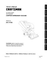
247.77763
Brand: Craftsman Pages: 48

CHIP-N-VAC 486.24717
Brand: Craftsman Pages: 28

YD
Brand: York Pages: 20

YD Series
Brand: York Pages: 150

YD
Brand: York Pages: 24

YCWJ45EE0
Brand: York Pages: 104


