


October 2005
RLC-SVX07A-EN
© American Standard Inc. 2005
Models
RTWA-70
RTUA-70
RTCA-70
RTWA-80
RTUA-80
RTCA-80
RTWA-90
RTUA-90
RTCA-90
RTWA-100
RTUA-100
RTCA-100
RTWA-110
RTUA-110
RTCA-110
RTWA-125
RTUA-125
RTCA-125
Installation
Operation
Maintenance
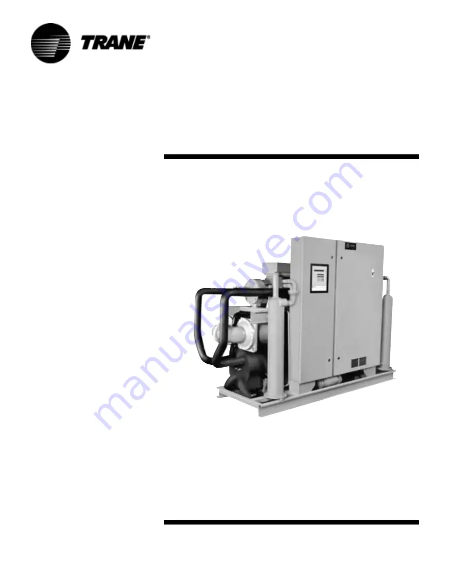
Series R
®
Rotary Liquid Chillers
Water-Cooled and Condenserless
Packaged Water-Cooled Chiller,
RTWA 70-125
Water-Cooled Compressor
Chiller RTUA 70-125
Air-Cooled Condenser
RTCA 70-125
Summary of Contents for R Series
Page 17: ...RLC SVX07A EN 17 Installation Mechanical Figure 2 Rigging and Lifting for RTWA Units ...
Page 22: ...22 RLC SVX07A EN Installation Mechanical Figure 7 Rigging and Lifting for RTUA Units ...
Page 25: ...RLC SVX07A EN 25 Installation Mechanical Figure 10 Rigging and Lifting for RTCA Condenser ...
Page 69: ...RLC SVX07A EN 69 Installation Electrical Figure 28 Interconnecting Wiring from RTUA to RTCA ...
Page 129: ...RLC SVX07A EN 129 Start Up Procedures Figure 41 RTWA Unit Sequence of Operation ...
Page 130: ...130 RLC SVX07A EN Start Up Procedures Figure 42 RTUA Unit Sequence of Operation ...
Page 154: ...154 RLC SVX07A EN Diagnostics ...
Page 156: ...156 RLC SVX07A EN 3332 ...
Page 158: ...158 RLC SVX07A EN 3333 ...
Page 160: ...160 RLC SVX07A EN 3334 ...
Page 162: ...162 RLC SVX07A EN 3335 ...
Page 164: ...164 RLC SVX07A EN 3336 ...
Page 166: ...166 RLC SVX07A EN 5119 ...
Page 168: ...168 RLC SVX07A EN 5143 ...
Page 170: ...170 RLC SVX07A EN 5144 ...
Page 172: ...172 RLC SVX07A EN 5145 ...
Page 174: ...174 RLC SVX07A EN 5146 ...
Page 176: ...176 RLC SVX07A EN 6008 ...
Page 178: ...178 RLC SVX07A EN 6009 ...
Page 180: ...180 RLC SVX07A EN 5147 ...
Page 182: ...182 RLC SVX07A EN 6526 ...
Page 184: ...184 RLC SVX07A EN 5150 ...
Page 186: ...186 RLC SVX07A EN 6010 ...


