


Smart Screen
THIS IS FRAGILE - read instructions before use and connect up with Power OFF!
Introduction
The Smart Screen simulates the display screens found in many railway stations and on board
trains, as well as other places such as motorways, buses, bus stops and sports stadiums.
You can customise and display your own messages and the module can store 10 different screens,
each with 2 lines of text, the top line with the option to include a clock and the bottom line capable
of much longer text which scrolls automatically when the sentence is wider than the screen.
Your own messages need to be programmed into the screen using a DCC controller, but once set
up they can be powered by either DC or DCC, and each message can be controlled in a number of
ways including Track Sensors, Loco direction, DCC commands, Switches or cycling the messages.
We have tried to make it as easy to set up and use as possible, but DCC controllers were never
designed to set up message displays and because there are so many options it is best to plan your
message before starting to program. Should you make mistakes while setting up, or want to change
messages later, you can edit messages or completely clear the whole screen and start again.
Function keys are used to enter most text and control options, so if you have a choice of DCC
controllers available to you, if possible choose one with 10 individual function keys F0 to F9 which
are easy to use by a single press, rather than multiple button shifts to enter each function.
This booklet contains 5 projects which will help you understand what the Smart Screen can do.
Getting Started
The Smart Screen is
very fragile
and should always be handled with care. The screen itself is
made of thin glass and so care must be taken not to put it under any stress, especially making sure
you rest the screen face down on a completely flat and clean surface when soldering terminals - a
piece of expanded polystyrene from packaging can make a good base on which to work.
The first thing you need to do is wire it up for which you will need a 15-25 watt fine tipped soldering
iron and solder, together with some wire cutters and strippers. A length of fine PTFE insulated wire
is included and is easy to conceal into your own models or one of the optional screen enclosures.
Prepare a completely clean, flat soft surface to work on and start by carefully removing the screen
from this booklet by gently peeling the paper away from the back of the screen, not the other way
round - we suggest the protective screen film is left on until you are ready to fit it on your layout.
Getting connected
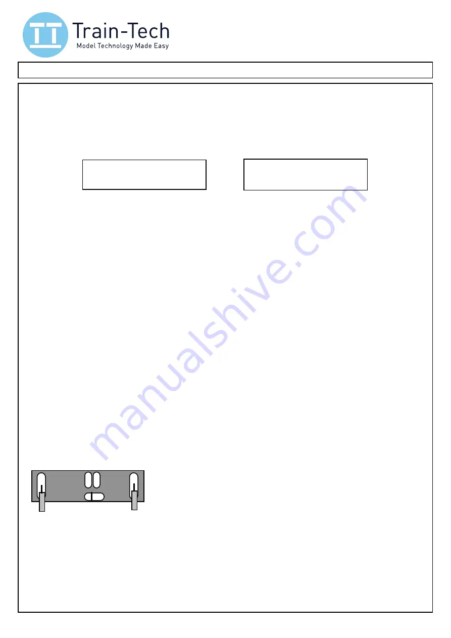
Turning the screen glass side down onto a flat clean surface you will see the following connections:
"
"
"
"
"
P & P are the Power input solder ‘pads’
"
"
"
"
"
A & B are control input solder ‘pads’ for Track Sensors or switches
"
"
"
"
"
C is the common input solder ‘pad’
"
"
"
"
"
L is Address reset ‘pad’ - do not solder!
"
"
"
"
"
"
Start by soldering wires flush onto the P power solder pads -
solder quickly
in 1-2 seconds max
and do not apply too much solder to ensure it remains slim, especially if mounting in an enclosure.
Turn the screen over and when you are ready to set the screen up connect the two power wires to
the DCC controller
regular track output
and turn on when you should see the demo come on the
screen (or if you just want to see the demo you can connect a 9V battery or 9-16 volt smooth dc).
A demo is preloaded into each new screen but deletes itself as soon as you program it.
You are now ready to plan and setup the Smart Screen with your messages - see following pages.
1
12:50: Norwich 12:47
Calling at Acle, Lingwood, B
12:50: Norwich 12:48
roaching *** Train now app
"
A B
P
"
"
"
P
© Train
Tech.com
"
L
"
C
Connect to 9-16v dc or DCC


