background image

010B2

19

A54988

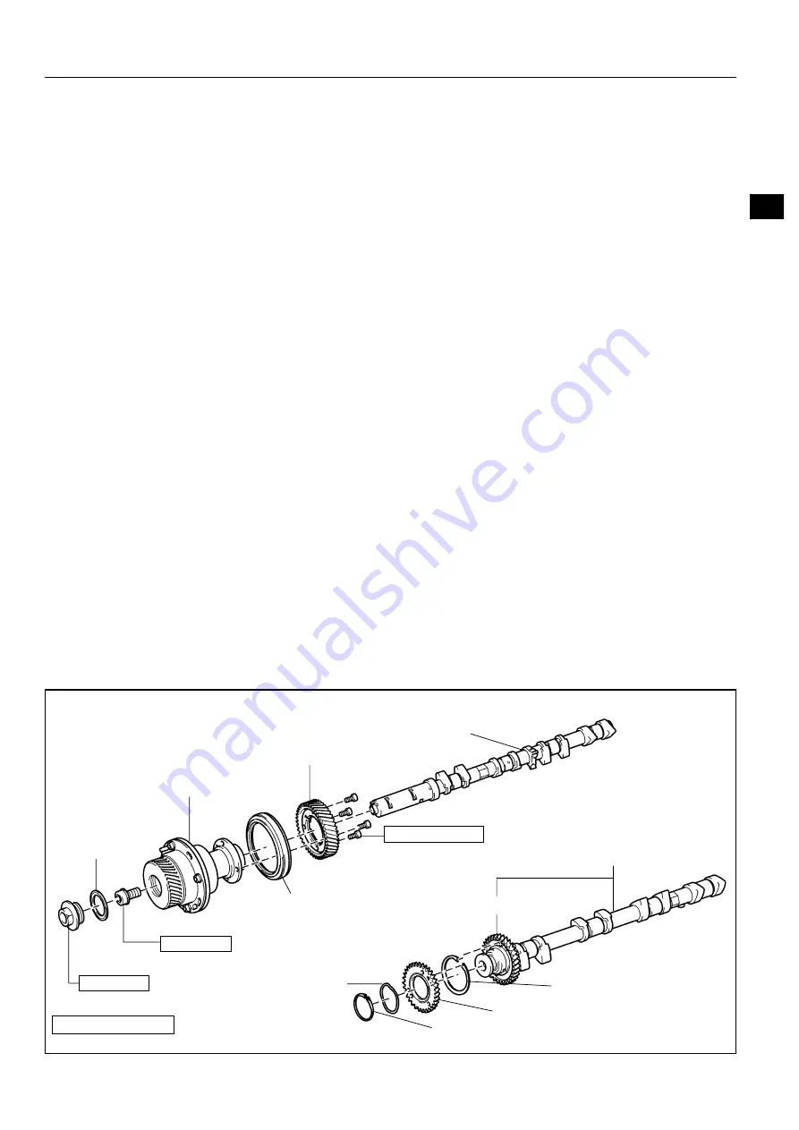
N·m (kgf·cm, ft·lbf) : Specified torque

z

Non

reusable part

Camshaft Timing Tube Assy

Camshaft Drive Gear

Seal Washer

z

Camshaft Setting Oil Seal

No. 2 Camshaft,
No. 4 Camshaft Sub

assy

Wave Washer

Camshaft Driven Main Gear

Snap Ring

Camshaft Timing Gear
Bolt Washer

Screw Plug

78 (790, 58)

15 (150, 11)

7.5 (80, 66 in.·lbf)

Camshaft Sub Gear

Camshaft,
No. 3 Camshaft Sub

assy

OVERHAUL

INTRODUCTION

HOW TO USE THIS MANUAL

01

1

1CD

FTV ENGINE REPAIR MANUAL (RM1046E)

HOW TO USE THIS MANUAL

GENERAL INFORMATION

1.

GENERAL DESCRIPTION

(a)

This manual is made in accordance with SAE J2008.

(b)

Generally, repair operations can be separated in the following 3 main processes:
1. Diagnosis
2. Removing and Installing, Replacing, Disassembling, Installing and Checking, Adjusting
3. Final Inspection

(c)

This manual explains the 1st process of ”Diagnosis” (placed in the ”Diagnostics” section), the 2nd pro-
cess of ”Removing and Installing, Replacing, Disassembling, Installing and Checking, Adjusting”, but
the 3rd process of ”Final Inspection” is omitted.

(d)

The following essential operations are not written in this manual. However, these operations must be
done in the practical situation.
(1)

Operation with a jack or lift

(2)

Cleaning of a removed part when necessary

(3)

Visual check

2.

INDEX

(a)

An alphabetical INDEX is provided as a section on the end of the book to guide you to the item to be
repaired.

3.

PREPARATION

(a)

Use of special service tools (SST) and special service materials (SSM) may be required, depending
on the repairing condition. Be sure to use SST and SSM when they are required and follow the working
procedure properly. A list of SST and SSM is in the Preparation section of this manual.

4.

REPAIR PROCEDURES

(a)

Component drawing is placed under the title when necessary.

(b)

Illustrations are placed as ”disassembled parts drawing” so that it enables you to understand the fitting
condition of the components.

(c)

Non

reusable parts, grease applied parts, precoated parts and tightening torque are specified in the

components drawing.

Example:

ProCarManuals.com

Summary of Contents for 1CD-FTV

Page 1: ...placing Disassembling Installing and Checking Adjusting but the 3rd process of Final Inspection is omitted d The following essential operations are not written in this manual However these operations must be done in the practical situation 1 Operation with a jack or lift 2 Cleaning of a removed part when necessary 3 Visual check 2 INDEX a An alphabetical INDEX is provided as a section on the end o...

Page 2: ...hod standard value and notice are placed g There may be a case where the illustrations of the similar models are used In that case the details may be different from the actual vehicle h The procedures are presented in a step by step format 1 The illustration shows what to do and where to do it 2 The task heading tells what to do 3 The detailed text tells how to perform the task and gives other inf...

Page 3: ...NUAL RM1046E 7 SI UNIT a The UNITS given in this manual are primarily expressed according to the SI UNIT International Sys tem of Unit and alternately expressed in the metric system and in the English System Example Torque 30 N m 310 kgf cm 22 ft lbf ProCarManuals com ...

Page 4: ... aluminum and rubber ex cylinder head cover gasket etc 2 Cleaning and washing by flushing oil ex kerosene white gasoline etc is prohibited S Parts made of rubber ex cylinder head cover gasket etc 4 POSITION AND DIRECTION OF EACH PARTS a Each parts needs to be reassembled as the same position and direction as it disassembled 1 Precautions at disassembly and reassembly S Follow the directions when t...

Page 5: ... the actual torque becomes excessive 2 In this text only the specified torque is described In case of using SST or extension tool find the read ing of the torque wrench by the formula 3 Formula T T x L2 L1 L2 T Reading of torque wrench N m kgf cm ft lbf T Torque N m kgf cm ft lbf L1 Length of SST or tool cm L2 Length of torque wrench cm 10 REMOVAL AND INSTALLATION OF FUEL CONTROL PARTS a Place for...

Page 6: ... the engine and turbo charger b When removing and installing of the inlet system parts close the opening of the removed inlet system parts and the engine with a clean shop lag or gum tape c When installing the inlet system parts check that there is no mixing of a metal tip 12 HANDLING OF HOSE CLAMPS a Before removing the hose check the depth of inserting portion and the clamp position to restore i...

Page 7: ...ssion Transaxle ATF Automatic Transmission Fluid AUTO Automatic AUX Auxiliary AVG Average AVS Adaptive Variable Suspension B Battery Voltage BA Brake Assist BACS Boost Altitude Compensation System BAT Battery BDC Bottom Dead Center B L Bi Level B S Bore Stroke Ratio BTDC Before Top Dead Center BVSV Bimetallic Vacuum Switching Valve CAN Controller Area Network CB Circuit Breaker CCo Catalytic Conve...

Page 8: ... ED Electro Deposited Coating EDU Electronic Driving Unit EDIC Electric Diesel Injection Control EFI Electronic Fuel Injection E G Engine EGR Exhaust Gas Recirculation EGR VM EGR Vacuum Modulator ELR Emergency Locking Retractor EMPS Electric Motor Power Steering ENG Engine ESA Electronic Spark Advance ETCS i Electronic Throttle Control System intelligent EVAP Evaporative Emission Control EVP Evapo...

Page 9: ...ea Network LB Liftback LCD Liquid Crystal Display LED Light Emitting Diode LH Left Hand LHD Left Hand Drive L H W Length Height Width LLC Long Life Coolant LNG Liquified Natural Gas LO Low LPG Liquified Petroleum Gas LSD Limited Slip Differential LSP PV Load Sensing Proportioning And Bypass Valve LSPV Load Sensing Proportioning Valve MAP Manifold Absolute Pressure MAX Maximum MIC Microphone MIL Ma...

Page 10: ...l Type Steering R F Reinforcement RFS Rigid Front Suspension RH Right Hand RHD Right Hand Drive RLY Relay ROM Read Only Memory Rr Rear RRS Rigid Rear Suspension RWD Rear Wheel Drive SDN Sedan SEN Sensor SICS Starting Injection Control System SOC State Of Charge SOHC Single Overhead Camshaft SPEC Specification SPI Single Point Injection SRS Supplemental Restraint System SSM Special Service Material...

Page 11: ...ndersize VCV Vacuum Control Valve VENT Ventilator VIN Vehicle Identification Number VPS Variable Power Steering VSC Vehicle Stability Control VSV Vacuum Switching Valve VTV Vacuum Transmitting Valve VVT i Variable Valve Timing intelligent w With WGN Wagon W H Wire Harness w o Without WU TWC Warm Up Three way Catalytic Converter WU OC Warm Up Oxidation Catalytic Converter 1st First 2nd Second 2WD T...

Page 12: ...nk Connector 2 Data Link Connector 3 1 Check Connector 2 Total Diagnosis Communication Link TDCL 3 OBD II Diagnostic Connector DTC Diagnostic Trouble Code Diagnostic Trouble Code DTM Diagnostic Test Mode ECL Engine Control Level ECM Engine Control Module Engine ECU Electronic Control Unit ECT Engine Coolant Temperature Coolant Temperature Water Temperature THW EEPROM Electrically Erasable Programm...

Page 13: ...S Oxygen Sensor Oxygen Sensor O2 Sensor O2S OBD On Board Diagnostic On Board Diagnostic System OBD OC Oxidation Catalytic Converter Oxidation Catalyst Convert OC CCo OP Open Loop Open Loop PAIR Pulsed Secondary Air Injection Air Suction AS PCM Powertrain Control Module PNP Park Neutral Position PROM Programmable Read Only Memory PSP Power Steering Pressure PTOX Periodic Trap Oxidizer Diesel Partic...

Page 14: ...Vacuum Switching Valve TVSV TWC Three Way Catalytic Converter Three Way Catalytic TWC Manifold Converter CCRO TWC OC Three Way Oxidation Catalytic Converter CCR CCo VAF Volume Air Flow Air Flow Meter VR Voltage Regulator Voltage Regulator VSS Vehicle Speed Sensor Vehicle Speed Sensor WOT Wide Open Throttle Full Throttle WU OC Warm Up Oxidation Catalytic Converter WU TWC Warm Up Three Way Catalytic...

Page 15: ...023FS 01 PREPARATION INTAKE 02 1 1CD FTV ENGINE REPAIR MANUAL RM1046E INTAKE PREPARATION SST 09992 00242 Turbocharger Pressure Gauge TURBOCHARGER SUB ASSY 1CD FTV From September 2003 ProCarManuals com ...

Page 16: ...010 Attachment CYLINDER HEAD ASSY 1CD FTV From September 2003 09223 15030 Oil Seal Bearing Replacer PARTIAL ENGINE ASSY 1CD FTV From September 2003 09223 46011 Crankshaft Front Oil Seal Replacer PARTIAL ENGINE ASSY 1CD FTV From September 2003 09248 55050 Valve Clearance Adjust Tool Set PARTIAL ENGINE ASSY 1CD FTV From September 2003 09248 05510 Valve Lifter Press PARTIAL ENGINE ASSY 1CD FTV From S...

Page 17: ...V From September 2003 09953 05020 Center Bolt 150 PARTIAL ENGINE ASSY 1CD FTV From September 2003 09954 05021 Claw No 2 PARTIAL ENGINE ASSY 1CD FTV From September 2003 09950 60010 Replacer Set CYLINDER HEAD ASSY 1CD FTV From September 2003 CYLINDER BLOCK ASSY 1CD FTV From September 2003 09951 00210 Replacer 21 CYLINDER HEAD ASSY 1CD FTV From September 2003 09951 00350 Replacer 35 CYLINDER BLOCK AS...

Page 18: ...ASSY 1CD FTV From September 2003 09992 00242 Turbocharger Pressure Gauge PARTIAL ENGINE ASSY 1CD FTV From September 2003 Recommended Tools 09042 00020 Torx Socket T40 PARTIAL ENGINE ASSY 1CD FTV From September 2003 SSM 08826 00080 Seal Packing Black or equivalent FIPG PARTIAL ENGINE ASSY 1CD FTV From September 2003 CYLINDER HEAD ASSY 1CD FTV From September 2003 08826 00100 Seal Packing 1282B THREE...

Page 19: ...on wrench 6 mm Hexagon wrench 8 mm Connecting rod aligner Cylinder gauge Dial indicator Feeler gauge Micrometer Precision straight edge Steel square Torque wrench Vernier calipers Dial indicator with magnetic base Slide calipers Wooden block Spring tester Plastigage Heater Dye penetrate Caliper gauge Reamer Plastic faced hammer Ridge reamer ProCarManuals com ...

Page 20: ...023F0 01 02 6 PREPARATION LUBRICATION 1CD FTV ENGINE REPAIR MANUAL RM1046E LUBRICATION PREPARATION Equipment Feeler gauge ProCarManuals com ...

Page 21: ...CD FTV From September 2003 09953 04020 Center Bolt 150 GENERATOR ASSY 1CD FTV From September 2003 09954 04010 Arm 25 GENERATOR ASSY 1CD FTV From September 2003 09955 04071 Claw No 7 GENERATOR ASSY 1CD FTV From September 2003 09957 04010 Attachment GENERATOR ASSY 1CD FTV From September 2003 09958 04011 Holder GENERATOR ASSY 1CD FTV From September 2003 09950 60010 Replacer Set GENERATOR ASSY 1CD FTV...

Page 22: ...AL RM1046E 09950 70010 Handle Set GENERATOR ASSY 1CD FTV From September 2003 09951 07100 Handle 100 GENERATOR ASSY 1CD FTV From September 2003 Equipment Ohmmeter Torque wrench Vernier calipers Pull scale V block Dial indicator with magnetic base ProCarManuals com ...

Page 23: ...al Recess Bolt Deep Recess Bolt Stud Bolt Weld Bolt Class 4T 5T 6T 7T 8T 9T 10T 11T No Mark w Washer No Mark No Mark w Washer SERVICE SPECIFICATIONS STANDARD BOLT 03 1 1CD FTV ENGINE REPAIR MANUAL RM1046E STANDARD BOLT HOW TO DETERMINE BOLT STRENGTH ProCarManuals com ...

Page 24: ...0 670 1 050 65 in lbf 13 26 48 76 6T 6 8 10 12 14 16 1 1 25 1 25 1 25 1 5 1 5 8 19 39 71 110 170 80 195 400 730 1 100 1 750 69 in lbf 14 29 53 80 127 9 21 44 80 125 90 210 440 810 1 250 78 in lbf 15 32 59 90 7T 6 8 10 12 14 16 1 1 25 1 25 1 25 1 5 1 5 10 5 25 52 95 145 230 110 260 530 970 1 500 2 300 8 19 38 70 108 166 12 28 58 105 165 120 290 590 1 050 1 700 9 21 43 76 123 8T 8 10 12 1 25 1 25 1 ...

Page 25: ... Washer No Mark No Mark Nut with 1 or more marks on one side surface of the nut SERVICE SPECIFICATIONS STANDARD BOLT 03 3 1CD FTV ENGINE REPAIR MANUAL RM1046E HOW TO DETERMINE NUT STRENGTH HINT Use the nut with the same number of the nut strength classification or the greater than the bolt strength clas sification number when tightening parts with a bolt and nut Example Bolt 4T Nut 4N or more ProC...

Page 26: ...RVICE SPECIFICATIONS INTAKE 1CD FTV ENGINE REPAIR MANUAL RM1046E INTAKE SERVICE DATA Actuator push rod Standard stroke 50 kpa 375 mmHg 15 in Hg 30 kpa 225 mmHg 9 in Hg 0 2 mm 0 008 in 5 0 mm 0 197 in ProCarManuals com ...

Page 27: ...mm 4 0197in 5 970 to 5 985 mm 0 2350 to 0 2356 in 0 9 0 035 in 0 6 mm 0 0236 in Exhaust valve Overall length Standard Minimum Valve stem diameter Margin thickness Standard Minimum 101 97 mm 4 0146in 101 55 mm 3 9980 in 5 960 to 5 975 mm 0 2346 to 0 2352 in 0 9 mm 0 035 in 0 6 mm 0 024 in Inner compression spring Free length Deviation Maximum Installed tension at 31 1 mm 1 224 in 40 45 mm 1 5925 in...

Page 28: ...o 31 027 mm 1 2211 to 1 2215 in Piston pin Piston pin diameter Oil clearance Standard 31 000 to 31 012 mm 1 2205 to 1 2209 in 0 005 to 0 019 mm 0 0002 to 0 0007 in Cylinder head set bolt Out side diameter Standard 10 40 to 11 00 mm 0 4094 to 0 4331 in Connecting rod bolt Diameter Standard 8 0 to 8 3 mm 0 315 to 0 315 in Connecting rod Out of alignment Maximum per 100 mm 3 94 in Rod twist Maximum p...

Page 29: ...l retainer x Cylinder head 9 8 100 7 2 Timing belt idler Sub assy No 2 x Oil pump 47 475 34 Timing belt idler No 1 x Cylinder head 35 357 26 Camshaft timing pulley x Camshaft 88 899 65 Exhaust fuel addition injector x Cylinder head 12 117 8 5 Nozzle holder clamp x Cylinder head 26 265 19 Nozzle leakage pipe x Cylinder head Hollow screw Flange bolt 16 20 163 204 12 15 Over flow screw x Plug 9 8 100...

Page 30: ...FICATIONS LUBRICATION 1CD FTV ENGINE REPAIR MANUAL RM1046E LUBRICATION SERVICE DATA Oil pump Tip clearance Standard Body clearance Standard 0 08 to 0 20 mm 0 0031 to 0 0079 in 0 10 to 0 20 mm 0 0039 to 0 0079 in ProCarManuals com ...

Page 31: ... 0 6 mm 0 024 in 0 2 mm 0 008 in Brush Brush lenght Standard Minimum 15 5 mm 0 610 in 10 0 mm 0 394 in Starter brush holder assy Spring installed load Standard 23 5 to 29 5 N 2 4 to 3 0 kgf 5 3 to 6 6 lbf Generator rotor assy Rotor coil resistance at 20_C 68_F Slip ring diameter Standard Minimum 2 3 to 2 7 W 14 2 to 14 4 mm 0 559 to 0 567 in 14 0 mm 0 551 in Generator brush holder assy Brush expos...

Page 32: ...frame assy 6 0 61 53 in lbf Magnetic switch x Starter drive housing assy 2 3 23 20 in lbf Magnetic switch x Lead wire 5 9 60 52 in lbf Generator drive end frame assy x Retainer plate 2 3 23 20 in lbf Generator coil assy x Generator drive end frame assy 5 8 59 51 in lbf Generator brush holder assy x Generator coil assy 1 8 18 16 in lbf Generator rear end cover x Generator coil assy 4 6 47 41 in lbf...

Page 33: ...that the turbine shaft turns smoothly If the turbine shaft does not turn or it turns with heavy drag re place the turbocharger 2 INSPECT ACTUATOR OPERATION a Apply vacuum of 66 kPa 500 mmHg 20 in Hg then raise the actuator push rod b Lower the vacuum then check the stroke when the vacu um is at the following values Standard stroke 50 kPa 375 mmHg 15 in Hg 0 2 mm 0 008 in 30 kPa 225 mmHg 9 in Hg 5 ...

Page 34: ...ap Sub assy Plate Washer Camshaft Timing Pulley Timing Belt Idler Sub assy No 1 13 135 10 20 204 15 88 899 65 N m kgf cm ft lbf Specified torque z Non reusable part 18 184 13 27 275 20 8 8 90 78 in lbf 35 357 26 Camshaft Carrier x5 x4 z O ring z Injection Nozzle Seat Injector Assy 20 204 15 20 204 15 ENGINE MECHANICAL PARTIAL ENGINE ASSY 1CD FTV From September 2003 14 1 1CD FTV ENGINE REPAIR MANUA...

Page 35: ...ler Sub assy No 2 Plate Washer x18 Crankshaft Timing Pulley Exhaust Fuel Addition Injector Assy Nozzle Holder Clamp z O ring z Gasket 12 117 8 5 N m kgf cm ft lbf Specified torque z Non reusable part 47 475 34 14 2 ENGINE MECHANICAL PARTIAL ENGINE ASSY 1CD FTV From September 2003 1CD FTV ENGINE REPAIR MANUAL RM1046E ProCarManuals com ...

Page 36: ...bf Oil Pan Sub assy No 2 z Non reusable part N m kgf cm ft lbf Specified torque 7 4 75 65 in lbf 33 331 24 Oil Regulator Assy 21 209 15 Oil Pan Insulator 7 5 77 66 in lbf 12 119 9 34 350 25 13 133 10 31 320 23 11 112 8 31 320 23 x7 x9 21 214 15 11 112 8 x6 x6 x6 42 428 31 x2 x2 12 119 9 x16 12 119 9 11 112 8 z Gasket Apply MP grease ENGINE MECHANICAL PARTIAL ENGINE ASSY 1CD FTV From September 2003...

Page 37: ...SEAL a Using a screwdriver pry out the 4 nozzle holder seals 3 REMOVE CYLINDER HEAD COVER SUB ASSY a Remove the 10 bolts cylinder head cover and gasket 4 REMOVE NOZZLE LEAKAGE PIPE ASSY a Remove the 4 hollow screws and bolt b Remove the nozzle leakage pipe and 4 gaskets from the cylinder head and injector 5 REMOVE NOZZLE HOLDER CLAMP a Remove the 4 bolts 4 washers and 4 nozzle holder clamps ProCar...

Page 38: ...ASSY a Using a Torx socket wrench T40 remove the Torx screw b Remove the nozzle holder clamp addition injector and gasket 8 REMOVE CAMSHAFT TIMING PULLEY a Using SST remove the pulley bolt SST 09960 10010 09962 01000 09963 01000 b Remove the timing pulley HINT Using a plastic faced hammer tap out the pulley c Remove the set key 9 REMOVE TIMING BELT IDLER SUB ASSY NO 1 a Using an 8 mm hexagon wrenc...

Page 39: ... 05020 09954 05021 12 REMOVE CAMSHAFT OIL SEAL RETAINER a Remove the 4 bolts b Using a screwdriver remove the oil seal retainer by prying between the oil seal retainer and camshaft bearing cap 13 REMOVE WATER PUMP ASSY a Remove the 7 bolts water pump and gasket 14 REMOVE CAMSHAFT a Using several steps loosen and remove the 14 bearing cap bolts uniformly in the sequence shown in the illustra tion b...

Page 40: ...the cylinder head from the dowels on the cylinder block then place the cylinder head on wooden blocks on a work bench HINT To lift the cylinder head pry between the cylinder head and cyl inder block using a screwdriver NOTICE Be careful not to damage the contact surfaces of the cylin der head and cylinder block 17 REMOVE OIL PAN SUB ASSY NO 2 a Remove the 16 bolts and 3 nuts b Insert the blade of ...

Page 41: ...a Remove the bolt and oil pan insulator 21 REMOVE OIL PAN SUB ASSY a Remove the 19 bolts and 3 nuts b Using a screwdriver remove the oil pan by prying be tween the cylinder block and No 1 oil pan NOTICE Be careful not to damage the cylinder block and No 1 oil pan 22 REMOVE OIL PUMP ASSY a Remove the 9 bolts b Remove the oil pump by prying between the oil pump and main bearing cap using a screwdriv...

Page 42: ...o damage the oil seal retainer and main bearing cap 24 REMOVE OIL CHECK VALVE SUB ASSY a Using an 8 mm hexagon wrench remove the check valve and gasket 25 REMOVE CYLINDER BLOCK WATER DRAIN COCK SUB ASSY 26 REMOVE CAMSHAFT OIL SEAL a Using a screwdriver and hammer tap out the oil seal 27 INSTALL CAMSHAFT OIL SEAL a Using SST and a hammer tap in a new oil seal until its sur face is flush with the ca...

Page 43: ... oil seal lip NOTICE Keep the lip free of foreign objects 30 REMOVE ENGINE REAR OIL SEAL a Using a screwdriver and hammer tap out the oil seal 31 INSTALL ENGINE REAR OIL SEAL a Using SST and a hammer tap in a new oil seal until its sur face is flush with the rear oil seal retainer edge SST 09223 15030 09950 70010 09951 07100 b Apply multipurpose grease to a new oil seal lip NOTICE Keep the lip fre...

Page 44: ...the drain pipe faces downward 34 INSTALL OIL CHECK VALVE SUB ASSY a Using an 8 mm hexagon wrench install a new gasket and the check valve Torque 33 N m 331 kgf cm 24 ft lbf 35 INSTALL ENGINE REAR OIL SEAL RETAINER a Apply seal packing to the oil seal retainer as shown in the illustration Seal packing Part No 08826 00080 or equivalent NOTICE S Install a nozzle of which opening is cut to 2 to 4 mm 0...

Page 45: ...es and must be assembled within 15 minutes after applying seal packing Otherwise the material must be removed and reapplied S Immediately remove the nozzle from the tube then re install the cap b Install a new gasket to the oil pump c Pour 0 5 cm3 0 03 cu in or more of engine oil into the bushing of the cylinder block d Apply engine oil to the cylinder block side which contacts the oil pump driven...

Page 46: ...3 minutes and must be assembled within 15 minutes after applying seal packing Otherwise the material must be removed and reapplied S Immediately remove the nozzle from the tube then re install the cap b Install the oil pan with 19 bolts and 3 nuts Torque 42 N m 428 kgf cm 31 ft lbf for bolt A 21 N m 209 kgf cm 15 ft lbf for bolt B 11 N m 112 kgf cm 8 ft lbf for bolt C 11 N m 112 kgf cm 8 ft lbf fo...

Page 47: ...16 bolts and 3 nuts Tighten the bolts and nuts uniformly in several steps Torque 12 N m 119 kgf cm 9 ft lbf 41 INSTALL CYLINDER HEAD SUB ASSY a Measure the protrusion height of the piston heads 1 Clean the cylinder block with solvent 2 Set the piston to measure to slightly before the TDC 3 Place a dial indicator on the cylinder block then cali brate the dial indicator at 0 mm 0 in HINT S Place the...

Page 48: ... 1 05 to 1 15 mm 0 0413 to 0 0453 in 1 Find the highest protrusion height among the 4 measurement records It is used to select a new cyl inder head gasket 2 Select a new gasket among A to E using the matrix below New gasket matrix Piston Protrusion mm in Gasket Size 0 165 to 0 220 0 0065 to 0 0087 A 0 220 to 0 270 0 0087 to 0 0106 B 0 270 to 0 320 0 0106 to 0 0126 C 0 320 to 0 370 0 0126 to 0 0146...

Page 49: ...ps install and tighten the 18 cylin der head bolts uniformly in the sequence shown in the illustration Torque 45 N m 459 kgf cm 33 ft lbf HINT See the table below for the bolt length Bolt Type Bolt Length A 160 mm 6 30 in B 104 mm 4 09 in If the cylinder head bolt does not meet the specified torque re place the cylinder head bolt with a new bolt 4 Mark the front of the cylinder head bolt with pain...

Page 50: ...l to the cam and gear of the camshaft and the journal of the camshaft carrier c Engage the exhaust camshaft gear and intake camshaft gear by matching the alignment marks on each gear d Roll down the exhaust camshaft onto the bearing journals while engaging gears with each other e Install the camshaft bearing caps 1 Remove any old packing FIPG material from the No 5 camshaft bearing cap 2 Apply sea...

Page 51: ...pecification valve clearance mea surements They will be used later to select an adjusting shim to replace Valve clearance Cold Intake 0 20 to 0 30 mm 0 008 to 0 012 in Exhaust 0 35 to 0 45 mm 0 014 to 0 018 in 45 ADJUST VALVE CLEARANCE a Remove the adjusting shim 1 Turn the crankshaft so that the cam lobe located over the adjusting valve faces upward 2 Position the notch of the valve lifter toward...

Page 52: ...justing shim to replace by following the formula or the charts 1 Using a micrometer measure the thickness of the removed shim 2 Calculate the thickness of a new shim so that the valve clearance comes within the specified value HINT T Thickness of the removed adjusting shim A Measured valve clearance N Thickness of a new adjusting shim Intake N T A 0 25 mm 0 010 in Exhaust N T A 0 40 mm 0 016 in 3 ...

Page 53: ...900 0 1142 2 950 0 1161 3 000 0 1181 3 050 0 1201 3 100 0 1220 3 150 0 1240 3 200 0 1260 3 250 0 1280 3 300 0 1299 17 Intake valve clearance Cold 0 20 to 0 30 mm 0 008 to 0 012 in EXAMPLE The 2 800 mm 0 1102 in shim is installed and the measured clearance is 0 450 mm 0 0177 in Replace the 2 800 mm 0 1102 in shim with a new No 21 shim 14 20 ENGINE MECHANICAL PARTIAL ENGINE ASSY 1CD FTV From Septemb...

Page 54: ...900 0 1142 2 950 0 1161 3 000 0 1181 3 050 0 1201 3 100 0 1220 3 150 0 1240 3 200 0 1260 3 250 0 1280 3 300 0 1299 17 Exhaust valve clearance Cold 0 35 to 0 45 mm 0 014 to 0 018 in EXAMPLE The 2 800 mm 0 1102 in shim is installed and the measured clearance is 0 590 mm 0 0232 in Replace the 2 800 mm 0 1102 in shim with a new No 21 shim ENGINE MECHANICAL PARTIAL ENGINE ASSY 1CD FTV From September 20...

Page 55: ...ng to the oil seal retainer as shown in the illustration Seal packing Part No 08826 00080 or equivalent NOTICE S Install a nozzle of which opening is cut to 2 to 4 mm 0 08 to 0 16 in S The parts must be set within 3 minutes and must be assembled within 15 minutes after applying seal packing Otherwise the material must be removed and reapplied S Immediately remove the nozzle from the tube then re i...

Page 56: ...of the cam shaft b Align the keyway of the timing pulley with the key located on the camshaft then slide the pulley into place c Using SST install the pulley bolt SST 09960 10010 09962 01000 09963 01000 Torque 88 N m 899 kgf cm 65 ft lbf 52 INSTALL EXHAUST FUEL ADDITION INJECTOR ASSY a Install a new gasket to the cylinder head b Install a new O ring to the injector c Apply a light coat of engine o...

Page 57: ...f cm 19 ft lbf i Remove the 4 injection pipes 54 INSTALL NOZZLE LEAKAGE PIPE ASSY a Remove the bolt which is tightened at the center of the camshaft bearing cap No 4 b Install the nozzle leakage pipe and 4 new gaskets NOTICE When installing the gaskets pay attention to the mounting orientation Install the gasket so that the joint of the gasket comes within the ranges shown in the illustration c Ap...

Page 58: ... cm2 14 5 psi of pressure for 60 seconds to check that there are no bubbles from the pipe connection SST 09992 00242 3 After checking fuel leaks wipe off soapy water from the pipe connection 55 INSTALL CYLINDER HEAD COVER SUB ASSY a Remove any old packing FIPG material b Apply seal packing to the cylinder head Seal packing Part No 08826 00080 or equivalent c Install the gasket to the head cover d ...

Page 59: ...aring Coil z Non reusable part N m kgf cm ft lbf Piston Specified torque Connecting Rod Bearing See Page 14 43 1st 30 306 22 2nd Turn 90 z Snap Ring z Snap Ring Cylinder Block Oil Orifice Sub assy Oil Nozzle No 1 Piston Pin 9 0 92 78 in lbf 7 4 76 67 in lbf 115 1 173 85 14 42 ENGINE MECHANICAL CYLINDER BLOCK ASSY 1CD FTV FromSeptember 2003 1CD FTV ENGINE REPAIR MANUAL RM1046E CYLINDER BLOCK ASSY 1...

Page 60: ...f necessary replace the crank shaft 2 INSPECT CONNECTING ROD OIL CLEARANCE a Check the match marks on the connecting rod and cap to ensure correct reassembly b Remove the 2 connecting rod cap bolts c Using the 2 removed connecting rod cap bolts remove the connecting rod cap and lower bearing by wiggling the connecting rod cap right and left HINT Keep the lower bearing attached to the connecting ro...

Page 61: ... in several steps Torque 30 N m 306 kgf cm 22 ft lbf If any of the cap bolts does not meet the specified torque re place the connecting rod cap bolts k Mark the front of the cap bolt with paint l Retighten the cap bolts by 90_ as illustrated m Check that the painted mark is now at a 90_ angle to the front NOTICE Do not turn the crankshaft n Remove the 2 bolts connecting rod cap and lower bear ing ...

Page 62: ...3 500 to 53 506 mm 2 1063 to 2 1065 in Mark 2 53 506 to 53 512 mm 2 1065 to 2 1068 in Mark 3 53 512 to 53 518 mm 2 1068 to 2 1070 in Crankshaft crank pin diameter Mark 0 50 494 to 50 500 mm 1 9880 to 1 9882 in Mark 1 50 488 to 50 494 mm 1 9877 to 1 9880 in Mark 2 50 482 to 50 488 mm 1 9875 to 1 9877 in Standard size bearing center wall thickness Mark 1 1 478 to 1 481 mm 0 0582 to 0 0583 in Mark 2 ...

Page 63: ...Oversize 0 125 2 743 to 2 793 mm 0 1080 to 0 1100 in Oversize 0 250 2 805 to 2 855 mm 0 1104 to 0 1124 in 6 REMOVE CRANKSHAFT a Uniformly loosen and remove the 10 main bearing cap bolts b Using the removed main bearing cap bolts wiggle the cap back and forth then remove the 5 main bearing caps 5 lower bearings and 2 lower thrust washers the No 3 main bearing cap only HINT S Keep the lower bearing ...

Page 64: ...ng NOTICE Try to keep the piston ring expansion as small as possible b Remove the coil by hand HINT Arrange the piston rings in the correct order 10 REMOVE W PIN PISTON SUB ASSY a Using a small screwdriver pry the snap rings off the pis ton b Gradually heat the piston up to approximately 60_C 140_F c Using a plastic faced hammer and brass bar lightly tap out the piston pin and remove the connectin...

Page 65: ...05 mm 0 0020 in If the warpage is greater than maximum replace the cylinder block 12 INSPECT CYLINDER BORE DIAMETER a Using a cylinder gauge measure the cylinder bore diame ter at positions A B and C in the thrust and axial direc tions Standard diameter 82 200 to 82 400 mm 3 2362 to 3 2441 in If the diameter is greater than maximum replace the cylinder block 13 INSPECT W PIN PISTON SUB ASSY a Usin...

Page 66: ...27 mm 1 2211 to 1 2215 in d Using a micrometer measure the piston pin diameter Piston pin diameter 31 000 to 31 012 mm 1 2205 to 1 2209 in e Subtract the piston pin diameter measurement from the bushing inside diameter measurement Standard oil clearance 0 005 to 0 019 mm 0 0002 to 0 0007 in If the oil clearance is greater than maximum replace the con necting rod If necessary replace the piston and...

Page 67: ... 0 0045 in Oil 0 03 to 0 07 mm 0 0012 to 0 0028 in If the clearance is not as specified replace the piston 16 INSPECT PISTON RING END GAP a Using a piston push the piston ring until it is a little below the bottom of the ring travel 110 mm 4 33 in from the top of the cylinder block b Using a feeler gauge measure the end gap Standard end gap No 1 0 27 to 0 39 mm 0 0106 to 0 0514 in No 2 0 39 to 0 5...

Page 68: ...If the circle runout is greater than maximum replace the crank shaft c Using a micrometer measure the diameter of each main journal and crank pin Main journal diameter 56 992 to 57 010 mm 2 2438 to 2 2445 in Crank pin diameter 50 482 to 50 500 mm 1 9875 to 1 9882 in If the diameter is not as specified replace the crankshaft d Check each main journal and crank pin for taper and out of round as illu...

Page 69: ... the bearing claw with the claw groove of the cylinder clock then push in the 5 upper bearings 2 Align the bearing claw with the claw groove of the main bearing cap then push in the 5 lower bear ings c Install the 2 thrust washers under the No 3 journal posi tion of the cylinder block with the oil grooves facing out ward d Install the 2 thrust washers on the No 3 bearing cap with the oil grooves f...

Page 70: ... to the threads and under the heads of the main bearing cap bolts i Install and uniformly tighten the 10 bolts of the main bear ing cap in several steps Torque 115 N m 1 173 kgf cm 85 ft lbf NOTICE Do not turn the crankshaft j Remove the bearing cap k Measure the Plastigage at its widest point Standard oil clearance 0 032 to 0 100 mm 0 0013 to 0 0039 in If the oil clearance is greater than maximum...

Page 71: ...haft Use Bearing 1 0 1 1 1 2 1 2 3 2 0 2 2 1 3 2 2 4 3 0 3 3 1 4 3 2 5 HINT EXAMPLE Cylinder block 2 Crankshaft 1 Total number 3 Use bear ing 3 Cylinder block main journal bore diameter Mark 1 61 000 to 61 006 mm 2 4016 to 2 4018 in Mark 2 61 006 to 61 012 mm 2 4018 to 2 4020 in Mark 3 61 012 to 61 018 mm 2 4020 to 2 4023 in Crankshaft main journal diameter Mark 0 57 004 to 57 010 mm 2 2443 to 2 2...

Page 72: ...UAL RM1046E 21 INSTALL TIGHT PLUG a Apply adhesive around new tight plugs Adhesive Part No 08833 00070 THREE BOND 1324 or equivalent b Using SST tap in the tight plugs as shown tn the illustra tion SST 09950 60010 09951 00350 09950 70010 09951 07100 Standard depth 2 0 mm 0 079 in for intake side 2 0 mm 0 079 in for exhaust side 1 5 mm 0 059 in for front side 1 5 mm 0 059 in for rear side A 2 0 mm ...

Page 73: ...B Protrusion Height 5 0 mm 0 197 in Protrusion Height 13 mm 0 512 in B A 14 56 ENGINE MECHANICAL CYLINDER BLOCK ASSY 1CD FTV FromSeptember 2003 1CD FTV ENGINE REPAIR MANUAL RM1046E 22 INSTALL RING PIN a Using a plastic faced hammer tap in new ring pins until their protrusion heights are as specified ProCarManuals com ...

Page 74: ...CYLINDER BLOCK ASSY 1CD FTV FromSeptember 2003 14 57 1CD FTV ENGINE REPAIR MANUAL RM1046E 23 INSTALL STRAIGHT PIN a Using a plastic faced hammer tap in new straight pins Standard protrusion 13 mm 0 5118 in for straight pin A 4 0 mm 0 1575 in for straight pin B 5 0 mm 0 1968 in for straight pin C 24 INSTALL STUD BOLT a Install the stud bolts as shown in the illustration Torque 2 9 N m 30 kgf cm 27 ...

Page 75: ...h the 4 bolts Torque 7 4 N m 75 kgf cm 65 in lbf 27 INSTALL CRANKSHAFT a Install the bearing on the cylinder block and bearing cap HINT Each upper bearing has an oil groove and oil hole and each low er bearing does not 1 Align the bearing claw with the claw groove of the cylinder block then push in the 5 upper bearings 2 Align the bearing claw with the claw groove of the main bearing cap then push...

Page 76: ...o the threads and under heads of the main bearing cap bolts f Install and uniformly tighten the 10 bolts of the main bear ing cap in several steps Torque 115 N m 1 173 kgf cm 85 ft lbf g Check that the crankshaft turns smoothly 28 INSTALL W PIN PISTON SUB ASSY a Install a new snap ring on one side of the piston pin hole b Gradually heat the piston up to approximately 60_C 140_F c Coat the piston p...

Page 77: ... piston ring expander install the oil ring HINT Align the oil ring so its end faces the opposite of the coil joint c Using a piston ring expander install the No 2 and No 1 piston rings with the code mark facing upward Code mark No 1 1T No 2 2T NOTICE Try to keep the piston ring expansion as small as possible d Position the piston rings so that the ring ends are as illus trated 31 INSTALL PISTON SU...

Page 78: ... Apply a light coat of engine oil to the threads and under heads of the connecting rod cap bolts g Install and alternately tighten the 2 cap bolts in several steps Torque 30 N m 306 kgf cm 22 ft lbf If any of the cap bolts does not meet the specified torque re place the connecting rod cap bolts h Mark the front of the cap bolt with paint i Retighten the cap bolts by 90_ as illustrated j Check that...

Page 79: ...E WATER PUMP ASSY 1CD FTV From September 2003 INSPECTION 1 INSPECT WATER PUMP ASSY a Visually check the drain hole for coolant leakage If leakage is found replace the water pump b Turn the pulley then check that the water pump bearing moves smoothly without making a noise If necessary replace the water pump ProCarManuals com ...

Page 80: ...SPECT OIL PUMP ASSY a Inspect the tip clearance 1 Using a feeler gauge measure the clearance be tween the drive and driven rotor tips Standard tip clearance 0 08 to 0 20 mm 0 0031 to 0 0079 in b Inspect the body clearance 1 Using a feeler gauge measure the clearance be tween the driven rotor and body Standard body clearance 0 1 to 0 20 mm 0 0039 to 0 0079 in ProCarManuals com ...

Page 81: ...e Assy Planetary Gear Starter Pinion Drive Lever Rubber Seal N m kgf cm ft lbf Specified torque 2 3 23 20 in lbf 5 9 60 52 in lbf 6 0 61 53 in lbf 6 0 61 53 in lbf Starter Magnetic Switch Assy 3 8 39 33 in lbf Grease application STARTING CHARGING STARTER ASSY 1CD FTV From September 2003 19 1 1CD FTV ENGINE REPAIR MANUAL RM1046E STARTER ASSY 1CD FTV From September 2003 COMPONENTS ProCarManuals com ...

Reviews: