background image

1

READ THROUGH THIS MANUAL

BEFORE STARTING CONSTRUCTION.

IT CONTAINS IMPORTANT INSTRUCTIONS 

AND WARNINGS CONCERNING THE 

ASSEMBLY AND USE OF THIS MODEL.

Tow e r 
Hobbies

®


guarantees 
this kit to be 
free from defects 
in  both  material  and 
workmanship at the 
date of purchase. This 
warranty does not cover any 
component parts damaged by 
use or modification. In no case shall 
Tower Hobbies’ liability exceed the 
original cost of the purchased kit. Further, 
Tower Hobbies reserves the right to change 
or modify this warranty without notice.

In that Tower Hobbies has no control over the final 
assembly or material used for final assembly, no 
liability shall be assumed nor accepted for any damage 
or injury resulting from the use by the user of the final 
user-assembled product. By the act of using the user-assembled 
product, the user accepts all resulting liability.

If the buyer is not prepared to accept the liability associated with the 
use of this product, the buyer is advised to return this kit immediately in 
new and unused condition to the place of purchase.

To make a warranty claim send the defective part or item to Hobby Services at 
the address below: (Visit hobbyservices.com for more information.)

Hobby Services • 3002 N. Apollo Dr.  Suite 1 • Champaign IL  61822 • USA

Include a letter stating your name, return shipping address, as much contact information as 
possible (daytime telephone number, fax number, e-mail address), a detailed description of 
the problem and a photocopy of the purchase receipt. Upon receipt of the package the problem 
will be evaluated as quickly as possible.

WA

R

R

A

N

TY

TOWA2030

© 

2016 Tower Hobbies.

®

  A subsidiary of Hobbico, Inc. 

®

®

TOWER HOBBIES

Champaign, Illinois

 (217) 398-8970 ext. 6
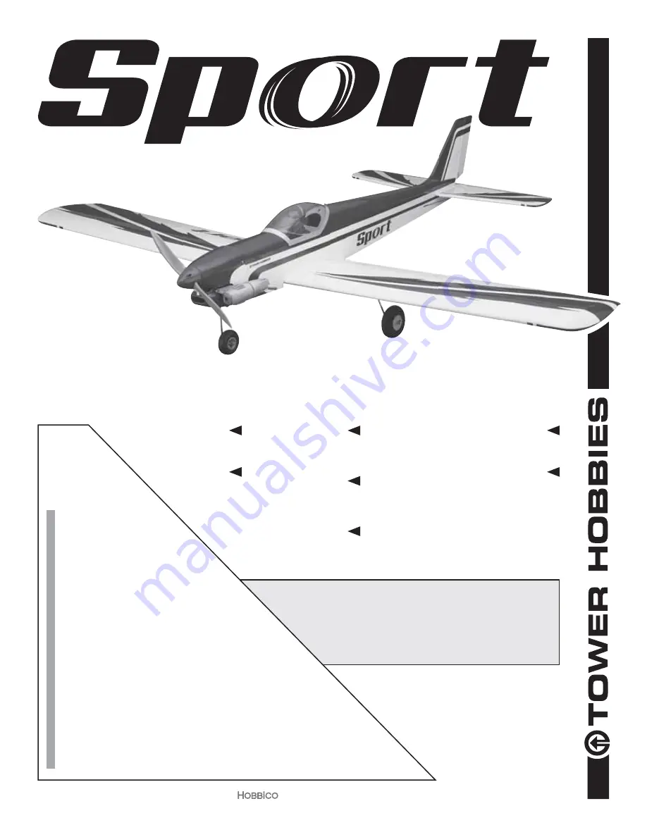
RADIO

4 – 5 channel

4 – 5  servos

WINGSPAN

60.2 in [1529mm]

WEIGHT

72 – 76 oz. [2041– 2155g]

WING AREA

592.8 sq in [38.24 dm

2

]

LENGTH

48.7 in [1237mm]

[email protected]

I N S T R U C T I O N   M A N U A L

WING LOADING

17.49 – 18.46 oz/ft

2

 [53 – 56 g/dm

2

]

POWER

.46 – .55 cu in [7.5 – 9.0cc] 2-stroke glow,

.70 cu in [11.5cc] 4-stroke glow,

Motor:  1.65" [42mm] 925W,

Castle Creations Edge Lite 75 ESC (not included)

ESC: 60A - 4S (not included)

Summary of Contents for SPORT

Page 1: ...oduct the buyer is advised to return this kit immediately in new and unused condition to the place of purchase To make a warranty claim send the defective part or item to Hobby Services at the address below Visit hobbyservices com for more information Hobby Services 3002 N Apollo Dr Suite 1 Champaign IL 61822 USA Include a letter stating your name return shipping address as much contact informatio...

Page 2: ...ervo extensions TACM2130 If mixing the aileron servos electronically with programmable mixing in the transmitter 2 6 150mm universal servo extensions TACM2092 If connecting the servos with a Y harness Futaba dual servo extension FUTM4130 If powering your Sport 46 EP with a brushless electric motor the BEC in the ESC may be used to power your receiver and servos so no receiver battery or on off rec...

Page 3: ... Mixing sticks GPMR8055 Threadlocker thread locking cement GPMR6060 Thin CA GPMR6001 Medium CA GPMR6007 CA applicator tips HCAR3780 CA accelerator GPMR6035 A Robart Super Stand II ROBP1402 is also indispensable for working on your Sport A covering iron with a cover sock may be required for tightening and re bonding covering to the model that may have loosened between the time the plane was manufac...

Page 4: ...e sheet balsa tail surfaces press down on the iron to thoroughly bond the covering to the balsa underneath If the covering blisters up over balsa and cannot be pressed back down the iron may be too hot or you are leaving it in one location for too long try reducing the heat or moving the iron a little faster 2 Give a generous tug on all control surfaces to check the hinges Add thin CA where necess...

Page 5: ...t Cut out 2 If necessary enlarge the servo cutout to fit your servo 3 Use the string to pull the aileron servo wire through the wing and fit the servo into the servo openings 4 Drill 1 16 1 6mm holes for the servo mounting screws in the wing and in the aileron for the control horn screws use care not to drill through the top of the aileron 1 16 1 5 mm Servo Arm 90º Connector 5 Enlarge the holes in...

Page 6: ...lat landing gear straps as a guide to drill 3 32 2 4mm holes into the landing gear block in the left wing 4 Enlarge the holes in the two landing gear straps with a 1 8 3 2mm drill 5 Mount the main landing gear to the rail in the wing with two straps and four M3 x 10 screws Trim the slots as needed so the wires fit flush 6 Mount the other landing gear and wheel to the other wing the same way Join t...

Page 7: ...in and join the wing half removing excess epoxy as it squeezes out 4 Use plenty of masking tape to tightly clamp the wing halves together and use a small clamp to clamp the front of the wing together at the leading edge tab Use the paper towel squares dampened with denatured alcohol to wipe away excess epoxy as you proceed Allow the epoxy to fully harden before removing the clamps and tape 5 Resid...

Page 8: ...to get the stab to align 6 Remove the stab and fin and prepare for gluing into the fuselage Typically the fin and stab are glued into the fuselage together An alternate method is to glue in the stab first clamping the fin fairing to the top of the stab with 1 4 6mm balsa not included for a perfectly tight glue joint If done this way be certain to temporarily position the fin to center the stab lat...

Page 9: ... a brushless motor cut the rest of the way through the partially cut air inlet in the firewall and remove the piece as shown in the photo in the following step 6 Cut the threaded end off another pushrod to a length of 16 400mm Make an L bend in one end of the pushrod and insert it into the guide tube for the nose steering 7 Assemble the nose gear as shown with the hardware indicated use threadlock...

Page 10: ...n the right side of the fuselage 2 Temporarily fasten the engine mount halves to the firewall with four M3 x 25 Phillips machine thread screws M3 lock washes and flat washers but do not fully tighten the screws yet 3 Place your engine on the mount Adjust the width of the mount halves to fit your engine then temporarily tighten the screws 4 Slide the engine forward or back so the drive washer or th...

Page 11: ...servo after the servo is installed later Install the Fuel Tank 1 Loosen the screw in the stopper in the fuel tank and take out the stopper fuel line assembly Check to make sure the clunks are present and secure on the lines and that the vent tube is pointed up toward the top of the tank Also make sure the lines on the clunks are not so long that the clunks can contact the back of the tank and poss...

Page 12: ...e ballast is required the tank may be removed for access to the hatch 5 Cut one of the fuel lines from either of the two tubes on the bottom of the tank to the correct length to fit the carburetor Leave the other two lines one for fueling defueling the other for the pressure vent line from the muffler the length they are now we ll cut them later after the cowl has been cut and fitted Proceed to Cu...

Page 13: ...the box together Use care not to get any CA on your fingers Do not build up large glue fillets until after the next step 5 Glue the triangle reinforcements around the back and front use medium CA and stick them into place with a hobby knife Reinforce all glue joints where necessary 6 Round the top forward corners of the motor mount box to clear the cowl as shown Mount the Brushless Motor 1 Mount t...

Page 14: ...it turns the correct direction If the motor turns the wrong direction swap any two of the three motor wires or reverse the motor direction in the ESC programming if available 5 Cut the 1 4 x 1 4 x 4 6 x 6 x 100mm balsa stick into two pieces and glue them across the back of the firewall as shown Cut the Cowl A No 569 or 570 Dremel grout removal bit and a sanding drum are indispensable for easily an...

Page 15: ... mount the engine back onto the engine mount Cover any access point into the engine where fiberglass dust could enter such as the carburetor and exhaust 5 There s no really fast easy way to cut holes in a cowl that fits tightly around an engine like this The best way is to install the cowl and little by little mark cut and re fit the cowl as necessary until it will go on over the engine We started...

Page 16: ...ne mark and cut the hole for the muffler This cowl was cut so that the muffler has to be installed after the cowl tightening the muffler bolts through holes cut in the opposite side of the cowl but another way is to cut all the way to the back of the cowl so it can be slipped past the muffler after it has been mounted to the engine ...

Page 17: ...wl can be positioned all the way over the engine and muffler it may be mounted to the fuselage 1 Use a straightedge and a fine point felt tip pen to mark the middle of the firewall down both sides of the fuselage The ink lines can be removed later with denatured alcohol but if you still prefer not to mark directly on the covering you can mark over strips of tape 2 Mark another line down both sides...

Page 18: ... the screw holes on the sides of the cowl 2 50mm ahead of the lines on the fuselage the top screws should be about 5 8 16mm down from the top of the fuselage and the bottom screws should be about 5 8 16mm up from the bottom of the fuselage 6 Once the screw hole locations have been marked double check to be sure the cowl is positioned to align with the spinner then drill the first cowl screw hole w...

Page 19: ...l the throttle servo if used and use another screw lock connector to connect the throttle pushrod to the throttle servo 8 Now that all the pushrods are connected drill 1 16 1 6mm holes in the servo tray for the servo screws Mount the servos with the screws that came with them 9 Mount the receiver and receiver battery if used with remaining hook and loop strap and R C foam rubber Mount an on off sw...

Page 20: ...lled and an empty fuel tank if using a glow engine If you ve installed a brushless motor leave the battery out of the plane but keep it handy for positioning on the bottom of the fuselage to determine where the battery should be mounted inside 2 If you ve installed a brushless motor reinstall the propeller and spinner 57mm 83mm 2 1 4 3 1 4 The recommended C G is 2 1 4 3 1 4 57mm 83mm back from the...

Page 21: ...t use your fingers to flip the propeller Make certain the glow plug clip or connector is secure so that it will not pop off or otherwise get into the running propeller Make all engine adjustments from behind the rotating propeller The engine gets hot Do not touch it during or right after operation Make sure fuel lines are in good condition so fuel will not leak onto a hot engine causing a fire To ...

Page 22: ...T If using multiple battery packs that are connected with an adapter never charge the batteries together through the adapter Always charge each battery pack separately Charge the batteries then read the following precautions on how to connect multiple packs for flying the model Battery Precautions There are two ways to connect multiple battery packs In Series and in Parallel This is a SERIES batte...

Page 23: ...pply to models while being flown indoors 7 I will not operate models with pyrotechnics any device that explodes burns or propels a projectile of any kind Radio Control 1 I will have completed a successful radio equipment ground check before the first flight of a new or repaired model 2 I will not fly my model aircraft in the presence of spectators until I become a qualified flier unless assisted b...

Page 24: ...sidiary of Hobbico Inc FORMULAS A 1 2 3 4 5 6 7 8 9 10 B C D E F G B A D x 8 E C B 1000 A 60 Flight Time 10ths Recharge Capacity mAh minute Battery Capacity Target Capacity to Use in Flight Recommended Flight Time Avg In Flight Current ...

Reviews: