background image

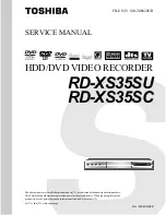
HDD/DVD VIDEO RECORDER

SERVICE MANUAL

Mar., 2006 GREEN

FILE NO.  810-200622GR

RD-XS35SU

RD-XS35SC

DIGITAL VIDEO

The above models are classified as green products (*1), as indicated by the underlined serial numbers.
This Service Manual describes replacement parts for the green products.  When repairing these green
product(s), use the part(s) described in this manual and lead-free solder (*2).

For (*1) and (*2), see the next page.

Summary of Contents for RD-XS35SC

Page 1: ...5SC DIGITAL VIDEO Theabovemodelsareclassifiedasgreenproducts 1 asindicatedbytheunderlinedserialnumbers ThisServiceManualdescribesreplacementpartsforthegreenproducts Whenrepairingthesegreen product s use the part s described in this manual and lead free solder 2 For 1 and 2 see the next page ...

Page 2: ...ement of parts is not only confined to manufacture The same green parts used in manufacture must also be used as replacement parts 2 LEAD FREE SOLDER This product is manufactured using lead free solder as a part of a movement within the consumer products industry at large to be environmentally responsible Lead free solder must be used in the servicing and repair of this product WARNING This produc...

Page 3: ... under license from Dolby Laboratories Dolby and the double D symbol are trademarks of Dolby Laboratories DTS and DTS Digital Out are trademarks of Digital Theater Systems Inc Manufactured under license from QSound Labs Inc U S patent Nos 5 105 462 5 208 860 and 5 440 638 and various foreign counterpart Copyright QSound Labs Inc 1998 2002 QXpanderTM is a trademark of QSound Labs Inc All rights res...

Page 4: ...ists the fault must be located and corrected Repeat the above test with the DVD VIDEO RECORDER power plug reversed NEVER RETURN A DVD VIDEO RECORDER TO THE CUSTOMER WITHOUT TAKING NECESSARY CORRECTIVE ACTION READING SHOULD NOT EXCEED 0 3V The lightning flash with arrowhead symbol within an equilateral triangle is intended to alert the user to the presence of uninsulated dangerous voltage within th...

Page 5: ...gram 4 4 3 Timer Circuit Diagram 4 4 4 Video Circuit Diagram 4 5 Tuner Unit Circuit Diagram 5 PC BOARDS 5 1 Front Jack PC Board 5 2 Front L PC Board 5 3 Front R PC Board 5 4 Tuner Unit PC Board 5 5 Digital PC Board 5 6 Mother PC Board CONTENTS SECTION 1 GENERAL DESCRIPTIONS 1 OPERATING INSTRUCTIONS 1 REPLACEMENT OF MECHANICAL PARTS 1 1 Cabinet Replacement 1 1 1 Top Cover 1 1 2 HDD 1 1 3 Front Pane...

Page 6: ...SECTION 1 GENERAL DESCRIPTIONS 1 OPERATING INSTRUCTIONS Please refer to the owner s manual about the contents SECTION 1 GENERAL DESCRIPTIONS ...

Page 7: ...Fig 1 2 1 2 2 Location of PC Boards Fig 1 2 2 ZG45 FAN RAM1 RAM DRIVE HDD1 HDD UNIT EU05 Mother PC Board EU02 Power PC Board EU01 Digital PC Board Board EU82 Tuner Unit PC Board EU03A Front R PC Board EU03B Front L F PC Board ar EU55 Front Jack PC Board ...

Page 8: ... missing or dropping etc always use a magnetized screwdriver in servicing Several kinds of screws are used and some of them need special cautions That is take care of the tapping screws securing molded parts and fine pitch screws used to secure metal parts If they are used improperly the screw holes will be easily damaged and the parts can not be fixed 1 REPLACEMENT OF MECHANICAL PARTS 1 1 Cabinet...

Page 9: ...le 3 and the connector 4 5 Remove four screws 5 then remove the damper 7 and HDD 8 from the bracket 6 Note Attach the tapes 1 as they were after the HDD is replaced Fig 2 1 2 Connector 4 Screws 5 Screws 5 Bracket 6 Damper 7 HDD 8 Flexible cable 3 Damper 7 Screws 2 Tape 1 Tape 1 Connector Claw Flexible cable 3 Damper 7 Damper 7 ...

Page 10: ...3 Disconnect two connectors 2 and two flexible cables 3 4 Remove two screws 4 four claws then remove the front panel 5 Note Attach the tape 1 as it was after the front panel is replaced Fig 2 1 3 Connector 2 Connector 2 Flexible cables 3 Front panel 5 Claws Claw Claw Screws 4 Tape 1 ...

Page 11: ...move two tapes 1 5 Disconnect two flexible cables 2 and the connector 3 6 Remove four screws 4 then remove the RAM drive 5 7 Remove the shield cover 6 from the RAM drive 5 Note Attach the tapes 1 as they were after the RAM drive is replaced Fig 2 1 4 Flexible cable 2 Connector 3 Shield cover 6 Tape 1 Tape 1 Screws 4 RAM drive 5 Flexible cable 2 ...

Page 12: ...emove the rear panel 5 5 Remove two screws 6 then remove the fan 7 Fig 2 1 5 1 1 6 Fan 1 Remove the top cover Refer to item 1 1 1 2 Disconnect the connector 1 3 Remove the cable tie 2 4 Remove two screws 3 then remove the fan 4 Fig 2 1 6 Screw 1 Screw 2 Screws 3 Screws 6 Fan 7 Power plug 4 Bushing Rear panel 5 Claw Claw Screws 3 Cable tie 2 Hexagonal nuts Fan 4 Connector 1 ...

Page 13: ...fer to item 1 1 1 2 Disconnect the two flexible cables 1 3 Disconnect the connector 2 4 Remove four screws 3 then remove the Digital PC board 4 Note Be careful when removing the Digital PC board as it is connected to the Mother PC board 5 with the four connectors 6 Fig 2 1 8 Screw 3 Claw Tuner Unit PC board 4 Screw 2 Flexible cable 1 Screws 3 Digital PC board 4 Flexible cables 1 Mother PC board 5 ...

Page 14: ...Remove the rear panel Refer to item 1 1 5 4 Remove the Tuner Unit PC board Refer to item 1 2 1 5 Remove the Digital PC board Refer to item 1 2 2 6 Disconnect the connector 1 7 Remove six screws 2 8 Draw the Mother PC board 3 backward direction of arrow to remove it Fig 2 1 9 Screws 2 Connector 1 Mother PC board 3 ...

Page 15: ...DD Refer to item 1 1 2 3 Remove the front panel Refer to item 1 1 3 4 Remove the RAM drive Refer to item 1 1 4 5 Disconnect the connector 1 and four connectors 2 6 Remove the bushing of the power plug 4 from the rear panel 3 7 Remove four screws 5 then remove the Power PC board 6 Fig 2 1 10 Power PC board 6 Power plug 4 Rear panel 3 Bushing Screws 5 Connectors 2 Connector 1 Connectors 2 ...

Page 16: ...e four screws 1 then remove the stay 2 4 Remove three screws 3 then remove the Front R PC board 4 5 Remove three screws 5 then remove the Front Jack PC board 6 6 Remove four screws 7 then remove the Front L PC board 8 Fig 2 1 11 Screws 7 Screws 3 Screws 5 Front L PC board 8 Front R PC board 4 Front panel Front Jack PC board 6 Screws 1 Stay 2 ...

Page 17: ...ete return the wiring to its original state by using the below diagram as a reference Fig 2 2 1 Flexible cable Tape Front Panel HDD RAM Drive Tuner Unit PC Board W003 W201 W001 W002 Power PC Board Mother PC Board Digital PC Board W006 W301 FAN W005 W202 W203 ...

Page 18: ...c and film capacitors of which capacitance are more than 10 pF None 5 or more B 0 1 C 0 25 D 0 5 F 1 G 2 2 Ceramic plastic and film capacitors of which capacitance are 10 pF or less None more than 5 pF B 0 1 pF C 0 25 pF 3 Electrolytic Trimmer Tolerance is not described Temperature characteristic None SL Ceramic capacitor For others temperature characteristics are described For capacitors of 0 01 ...

Page 19: ...forms for CD DVD and RF shown in the circuit diagrams are obtained when a test disc is played back All voltage values except the waveforms are expressed in DC and measured by a digital voltmeter 1 6 Others The parts indicated with NC or KETU etc are not used in the circuits of this model Eg 4 Eg 5 Fig 3 1 4 Fig 3 1 5 Type name 10µ Type Tolerance ...

Page 20: ... DATA5 DATA4 DATA10 GND GND 5V ON OFF 12V GND EVER 6V VKK Power_on0 CN701 GND GND GND ON OFF 37V GND ON OFF 1 5V ON OFF 1 5V ON OFF 1 5V ON OFF 1 5V ON OFF 3 3V ON OFF 3 3V ON OFF 1 5V ON OFF 1 5V ON OFF 3 3V ON OFF 3 3V ON OFF 5V GND GND GND LED_DVD_REC LED_HDD_PLAY B B B_DD15 B_DRESET D_GND B_DD12 LED_HDD_REC D 1 5V DATA13 GND 5V DATA11 DATA3 DATA12 DATA2 B_DD11 D1 5V GND 5V FL GND CN105 GND FL_...

Page 21: ...NGF6501GF uPD72852AGB 8EU A 1394 PHY uPD61181F1 181 MN2 A FRAME SYNC ENCODE ENCRIPT ATAPI DRV DECRIPT DECODE GRAPIC NTSC ENCODE MAIN CPU Audio D A Converter PCM1755 Audio Multi Decoder AN5832SA IR out 256Mbit DDR SDRAM x4 64kbit EEPROM 32Mbit FLASH ROM 64Mbit FLASH ROM x2 OUT_1 OUT IN_1 IN_2 IN_3 VHF UHF FL_Driver DT6315 Timer CPU uPD784225Y 4 0MHz OSC 32MHz OSC 27MHz S in C_Video in Audio in L R ...

Page 22: ...Fig 3 4 1 4 CIRCUIT DIAGRAMS 4 1 Power Supply Circuit Diagram ...

Page 23: ...Fig 3 4 2 4 2 Front Circuit Diagram 4 2 1 Front Circuit Diagram L R ...

Page 24: ...4 2 2 Front Jack Circuit Diagram Fig 3 4 3 ...

Page 25: ... capacitor Tantalum capacitor Tantalum capacitor Tantalum capacitor Place these parts together Place these parts together Tantalum capacitor Fig 3 4 4 4 3 Digital Circuit Diagram 4 3 1 Digital 1 Circuit Diagram ...

Page 26: ...4 3 Digital Circuit Diagram 4 3 1 Digital 1 Circuit Diagram ...

Page 27: ...Tantalum capacitor Tantalum capacitor Tantalum capacitor Tantalum capacitor ...

Page 28: ...pacitor pacitor Tantalum capacitor ...

Page 29: ......

Page 30: ......

Page 31: ......

Page 32: ...Place these parts together ...

Page 33: ...Place these parts together Fig 3 4 4 ...

Page 34: ...Fig 3 4 5 4 3 2 Digital 2 Circuit Diagram ...

Page 35: ...4 4 Mother Circuit Diagram 4 4 1 Tuner Circuit Diagram Fig 3 4 6 ...

Page 36: ...4 4 2 Audio Circuit Diagram Fig 3 4 7 ...

Page 37: ...4 4 3 Timer Circuit Diagram Fig 3 4 8 ...

Page 38: ...4 4 4 Video Circuit Diagram Fig 3 4 9 ...

Page 39: ...4 5 Tuner Unit Circuit Diagram Fig 3 4 10 ...

Page 40: ...1 3 4 A B C D E G 2 5 F 5 PC BOARDS 5 1 Front Jack PC Board Fig 3 5 1 EU55 Front Jack PC Board Top side Fig 3 5 2 EU55 Front Jack PC Board Bottom side ...

Page 41: ... 5 F 5 2 Front L PC Board Fig 3 5 3 EU03B Front L PC Board Top side Fig 3 5 4 EU03B Front L PC Board Bottom side 5 3 Front R PC Board Fig 3 5 5 EU03A Front R PC Board Top side Fig 3 5 6 EU03A Front R PC Board Bottom side ...

Page 42: ...06 JP007 JP008 JP009 JP0010 LB99 MB01 ZB99 1 2 3 A Fig 3 5 7 EU82 Tuner Unit PC Board Top side CB80 CB87 CB88 CB89 CB90 CB91 CB93 CB94 CB97 CB98 EB79 EB80 EB81 EB82 EB83 EB84 EB85 EB86 EB87 EB88 EB89EB90 EB91 EB92 EB93 EB94 EB95 EB96 EB97 EB98 EB99 LB96 LB97 LB98 QB99 RB20 RB21 RB91 RB92 RB93 RB95 RB96 RB97 RB98 RB99 1 2 3 A ...

Page 43: ...1 R472 R473 R474 R481 R482 R483 R484 R485 R486 R487 R488 R489 R490 R491 R492 R495 R496 R497 R498 R505 R506 R507 RM302RM303 RM306 RM307 RM308 RM313 RM315 RM316 RM317 RM318 RM320 RM321 RM322 RM323 RM324 RM325 RM326 RM327 RM328 RM331 RM332 RM333 RM336 RM339 RM340 RM342 RM343 RM344 RM345 RM346 RM347 RM348 RM349 RM352 RM353 X201 X301 X303 A B C D 1 2 3 C202 C203 C204 C205 C206 C207 C208 C209 C210 C213 ...

Page 44: ...8 JP129 JP130 JP131 JP132 JP133 JP134 JP135 JP136 JP137 JP138 JP139 JP140 JP141 JP142 JP143 JP144 JP145 JP147 JP148 JP149 JP150 JP151 JP152 JP153 JP155 JP156 JP157 JP158 JP159 JP160 JP161 JP162 JP163 JP164 JP165 JP166 JP167 JP168 JP169 JP171 JP172 JP173 JP174 JP175 JP176 JP177 JP178 JP179 JP180 JP182 JP183 JP184 JP185 JP186 JP187 JP188 JP189 JP190 JP191 JP192 JP193 JP194 JP195 JP196 JP197 JP199 JP...

Page 45: ...X21 EX22 EX23 EX30 EX31 EX32 EX33 EX34 EX35 EX36 EX37 EX38 EX62 EX63 EX64 EX65 EX98 EX99 IC700 IC701 IC702 IC901 IC902 ICA01 ICA03 ICB01 ICB10 ICW01 ICX01 ICX04 ICX31 ICX32 L701 L704 L705 L706 L901 LA11 LB06 Q700 Q701 Q702 Q904 Q905 Q906 Q908 QW02 QW03 QW04 QX06 QX09 QX31 QX32 R700 R701 R702 R703 R704 R705 R706 R707 R708 R709 R710 R711 R712 R713 R714 R715 R716 R717 R718 R719 R721 R722 R723 R724 R7...

Page 46: ...ocessing be sure to include the model number and description ABBREVIATIONS 1 Integrated Circuit IC 2 Capacitor Cap Capacitance Tolerance for Nominal Capacitance more than 10pF P 100 0 Symbol Tolerance B 0 1 C 0 25 D 0 5 F 1 G 2 J 5 K 10 M 20 N 30 V 20 10 W 100 10 U 75 10 Q 30 10 T 50 10 Symbol Tolerance X 40 20 Y 150 10 Z 80 20 Ex 10µF J 10µF 5 Symbol Tolerance pF B 0 1 C 0 25 D 0 5 F 1 G 2 Ex 10p...

Page 47: ...4 EXPLODED VIEWS 4 1 Packing Assembly Fig 4 4 1 ZF01 ZF35 ZF10 ZF11 ZF12 ZF13 Note The shape of the packing material is sometimes different ...

Page 48: ...4 2 Chassis Assembly Fig 4 4 2 EU01 W301 W003 W006 EU05 EU82 EU02 EU03A EU03B EU55 W002 ZG01 W001 W005 W501 ZG50 W202 RAM1 HDD1 ZG45 ZG20 W203 W201 W101 W102 MB01 ...

Page 49: ...0463190 WIRE 4P L370 HDD POWER W203 P000463200 WIRE 6P L320 RAM POWER W301 P000463110 CABLE ZHR 5P L130 FRONT J DIGITAL W501 P000463140 ATAPI FFC CONV UNIT YKF43 0025 ZF01 P000432480 Remote Control Unit SE R0144 ZF10 P000453930 OWNERS MANUAL ST ENGLISH RD XS35SU SC ZF10 P000453950 OWNERS MANUAL ST FRENCH RD XS35SC ZF11 P000453940 OWNERS MANUAL OP ENGLISH RD XS35SU SC ZF11 P000453960 OWNERS MANUAL ...

Page 50: ...YSTAL 2725T NSA5293C 27 0M X600 P000446160 OSCILLATOR CRYSTAL NX8045GB LN CF 001 32M EU02 P000432520 PC BOARD ASSY POWER EU03A P000463260 PC BOARD ASSY FRONT R INTEGRATED CIRCUITS IC101 P000416700 IC PT6315 IC102 P000434980 IC GP1UM271RK0F TRANSISTORS Q101 P000446250 Transistor Chip RN1401 Q102 P000446250 Transistor Chip RN1401 Q103 P000446250 Transistor Chip RN1401 Q104 P000446250 Transistor Chip...

Page 51: ...000446260 Transistor Chip RN1402 Q906 P000446210 Transistor Chip RN2402 Q908 P000446240 Transistor Chip HN1C03F B QW02 P000446260 Transistor Chip RN1402 QW03 P000446230 Transistor Chip 2SA1162 Y QW04 P000446230 Transistor Chip 2SA1162 Y QX06 P000446230 Transistor Chip 2SA1162 Y QX09 P000446230 Transistor Chip 2SA1162 Y QX31 P000446220 Transistor Chip 2SC2712 Y QX32 P000446260 Transistor Chip RN140...

Page 52: ... 1 at rear Y 1 0Vp p 75Ω Sync signal negative Mini DIN4 Pin x 3 systems C 0 286Vp p 75Ω 2 at rear 1 in front Y 1 0Vp p 75Ω Sync signal negative Mini DIN4 Pin x 1 system C 0 286Vp p 75Ω 1 at rear Y output green 1 0Vp p 75Ω Sync signal negative Pin jack x 1 system PB PR output blue red 0 7Vp p 75Ω Pin jack x 1 system each 2 0V rms 22kΩ or above pin jack L R x 3 systems 2 at rear 1 in front 2 0V rms ...

Page 53: ...1 1 SHIBAURA 1 CHOME MINATO KU TOKYO 105 8001 JAPAN ...

Reviews: