AIR CONDITIONER (MULTI TYPE)
Installation Manual
R410A
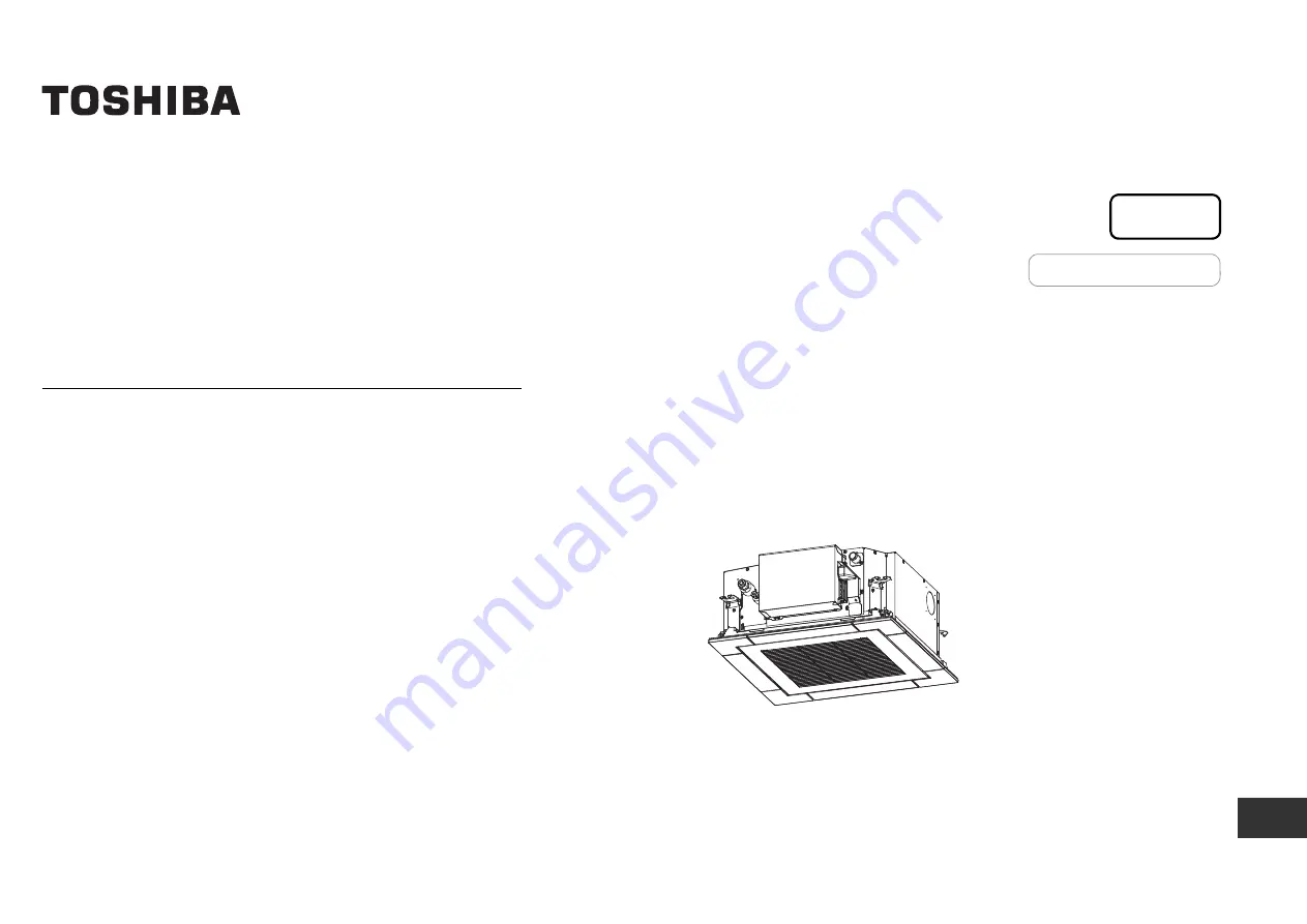
Indoor Unit
<Compact 4-way Cassette type>
MMU-UP0051MH-EMMU-UP0071MH-EMMU-UP0091MH-EMMU-UP0121MH-EMMU-UP0151MH-EMMU-UP0181MH-E
Model name:
For commercial use
English
Страница 1: ...TIONER MULTI TYPE Installation Manual R410A Indoor Unit Compact 4 way Cassette type MMU UP0051MH E MMU UP0071MH E MMU UP0091MH E MMU UP0121MH E MMU UP0151MH E MMU UP0181MH E Model name For commercial use English ...
Страница 2: ...Link are combined with models other than U series TCC Link the wiring specifications and maximum number of connectable indoor units will be changed Pay attentions to their communication specifications when carrying out the installation maintenance or repair For its details refer to the Electrical connection in this Manual Contents 1 Precautions for safety 3 2 Accessory parts 7 3 Selection of insta...
Страница 3: ...e knowledge related to these operations The qualified service person who is allowed to do the electrical work involved in installation repair relocation and removal has the qualifications pertaining to this electrical work as stipulated by the local laws and regulations and he or she is a person who has been trained in matters relating to electrical work on the air conditioners made by Toshiba Car...
Страница 4: ...fferent from the one specified for complement or replacement Otherwise abnormally high pressure may be generated in the refrigeration cycle which may result in a failure or explosion of the product or an injury to your body Before opening the intake grille of the indoor unit or service panel of the outdoor unit set the circuit breaker to the OFF position Failure to set the circuit breaker to the O...
Страница 5: ...f air conditioner otherwise it may cause imperfect combustion Installation When the indoor unit is to be suspended the designated hanging bolts M10 or W3 8 and nuts M10 or W3 8 must be used Install the air conditioner securely in a location where the base can sustain the weight adequately If the strength is not enough the unit may fall down resulting in injury Follow the instructions in the Instal...
Страница 6: ...t first conducting these checks If there is any kind of trouble such as check code display has appeared smell of burning abnormal sounds the air conditioner fails to cool or heat or water is leaking has occurred in the air conditioner do not touch the air conditioner yourself but set the circuit breaker to the OFF position and contact a qualified service person Take steps to ensure that the power ...
Страница 7: ...oil enter the refrigerating cycle during installation work To prevent charging an incorrect refrigerant and refrigerating oil the sizes of connecting sections of charging port of the main unit and installation tools are changed from those for the conventional refrigerant Accordingly the exclusive tools are required for the R410A refrigerant For connecting pipes use new and clean piping designed fo...
Страница 8: ...ed to air with high salt content seaside area or place exposed to large quantities of sulfide gas hot spring The unit should be used in these places special protective measures are needed A kitchen in restaurant or places around machines and equipment in a factory where a lot of oils are used Oil adhering to the heat exchanger and the resin parts in the indoor unit may lower the unit performance s...
Страница 9: ...k 200 200 15 or more 271 or more 1000 or more 271 or more 1000 or more 1000 or more An obstacle 15 or more 1 400 or more 560 or more 3 Check port 450 2 Check port 450 1000 or more Ceiling height Unit m When the height of the ceiling exceeds the distance of the item Standard 4 way in below table the warm air is difficult to reach the floor It is necessary to change the setup value of the high ceili...
Страница 10: ...on 580 to 594 13 to 20 Panel external dimension 620 13 to 20 13 to 20 Ceiling open dimension 580 to 594 Panel external dimension 620 Unit mm 23 5 0 146 191 320 214 256 93 40 132 173 257 70 53 193 154 146 8 3 12 184 A Ceiling open dimension 580 to 594 Bottom face of ceiling Wiring entry for remote control Unit external dimension 575 Refrigerant pipe connecting port Gas side Refrigerant pipe connect...
Страница 11: ...ccording to size in the unit external view as shown below Hanging bolt M10 or W3 8 4 pieces Nut M10 or W3 8 12 pieces Indoor unit Panel fixing screw Installation pattern Accessory Installation pattern attachment hole New concrete slab Install the bolts with insert brackets or anchor bolts Steel flame structure Use existing angles or install new support angles Existing concrete slab Use a hole in a...
Страница 12: ...two indoor units installed in a room to be respectively operated using two wireless remote controllers 7 m o r le s s 5 Drain piping CAUTION CAUTION Following the Installation Manual perform the drain piping work so that water is properly drained and apply a heat insulation so as not to cause a dew drop Inappropriate piping work may result in water leakage in the room and wet of furniture Piping H...
Страница 13: ...less Underside of ceiling Indoor unit 300 mm or less Rising up 850 mm or less After the electric work has finished pour water during COOL mode operation If the electric work has not yet finished pull out the float switch connector CN34 Red from the electrical control box and check draining by plugging the single phase 208 V to 240 V power to the terminal blocks L and N If doing so the drain pump m...
Страница 14: ...as side Liquid side UP005 to UP012 9 5 6 4 UP015 UP018 12 7 6 4 Outside diameter size mm R410A tool used Conventional tool used 6 4 9 5 0 0 5 1 0 1 5 12 7 15 9 Outside diameter size mm A 0 0 4 6 4 9 1 9 5 13 2 12 7 16 6 15 9 19 7 B A Tightening connection CAUTION CAUTION Do not apply excessive torque Otherwise the nut may crack depending on the conditions Tightening torque of flare pipe connection...
Страница 15: ...pipes completes Power supply wire and communication wires specifications Power supply wire and communication wires are locally procured For the power supply specifications follow to the table below If capacity is little it is dangerous because overheat or burnout may be caused For specifications of the power capacity of the outdoor unit and the power supply wires refer to the Installation Manual a...
Страница 16: ...re models other than U series their system diagrams for the wiring specifications are the same as the system diagram above SMMS u U series In the case of combining with outdoor units other than Super Modular Multi System u series SMMS u The length of the communication line L1 L2 L3 means the total length of the inter unit wire length between indoor and outdoor units added with the central control ...
Страница 17: ... Unit type Outdoor unit U series U series U series U series Indoor unit U series U series U series U series Remote controller Remote sensor U series U series U series U series Communication type TU2C Link TCC Link Max number of connectable units 16 8 L1 L L2 Ln Indoor unit Remote controller inter unit wiring Indoor unit Indoor unit Indoor unit Remote controller Remote controller wiring For number ...
Страница 18: ...twin connection Wire type Specification Cord clamping position Cabtyre cord 3 core stranded wire 2 5 mm Side D Cabtyre cord 2 core stranded wire 1 5 mm Side C Side D Space 8 5 mm Side C Space 4 mm Hook part Screws Cover of electrical control box CAUTION CAUTION 1 Make sure to fix the power supply wire with the cord clamp so that no water enters into the electrical control box through the power sup...
Страница 19: ...yclically Select the indoor unit to change settings for The fan of the selected indoor unit runs and the louvers start swinging The indoor unit can be confirmed for which to change settings 3 Push OFF timer button to confirm the selected indoor unit 4 Push the menu button to make Code No flash Change Code No with setting button 5 Push the menu button to make Set data flash Change Set data with set...
Страница 20: ...ory default 0003 5000 H 0004 10000 H Swing set data Swing of louvers 0001 Standard swing Factory default 0002 Dual swing 0003 Cycle swing 1 0001 2 0002 3 0003 5 0005 4 0004 Set data How to cancel louver lock Set the wind direction to 0000 of the louver lock setup procedure above When the setting is canceled goes out Other operations are the same as those in How to set up louver lock No swing To se...
Страница 21: ...usual 4 After the test run push OFF timer button to stop a test run TEST disappears on the display and the air conditioner enters the normal stop mode 4 3 1 2 3 Wireless remote controller 1 Turn on the power of the air conditioner When power is turned on for the first time after installation it takes approx 5 minutes until the remote controller becomes available In the case of subsequent power on ...
Страница 22: ...grille and remove Hook Fall preventive strap 4 Cleaning with water or vacuum cleaner If dirt is heavy clean the air filter using tepid water with a neutral detergent or just water After cleaning with water dry the air filter sufficiently in a shaded place 5 Mount the air filter 6 Close the air intake grille Check that the fall preventive strap of the air intake grille is attached to the panel In i...
Страница 23: ...earance Replace the fan when vibration or balance is terrible Brush or wash the fan when it is contaminated Air intake discharge grilles Indoor outdoor Dust dirt scratches Fix or replace them when they are deformed or damaged Drain pan Indoor Dust dirt clogging drain contamination Clean the drain pan and check the downward slope for smooth drainage Ceiling panel louvres Indoor Dust dirt scratches ...
Страница 24: ...unit side Indoor unit E06 E06 No of indoor units in which sensor has been normally received Decrease of No of indoor units I F E07 Communication circuit trouble between indoor outdoor unit Detected at outdoor unit side I F E08 E08 Duplicated indoor unit addresses Duplicated indoor unit addresses Indoor unit I F E09 Duplicated master remote controllers Remote controller E10 Communication trouble be...
Страница 25: ... 03 Comp 3 side Compressor break down Compressor inverter H02 H02 01 Comp 1 side 1 Comp 1 side 02 Comp 2 side 2 Comp 2 side 03 Comp 3 side Compressor trouble lock Compressor inverter H03 H03 01 Comp 1 side 1 Comp 1 side 02 Comp 2 side 2 Comp 2 side 03 Comp 3 side Current detect circuit system trouble Compressor inverter H04 H04 Comp 1 case thermostat operation I F H05 H05 TD1 sensor miswiring I F ...
Страница 26: ...2 Comp 2 side 2E Comp 2 side 03 Comp 3 side ALT Phase missing detection Power failure detection Inverter DC voltage trouble comp Inverter DC voltage trouble comp Inverter DC voltage trouble comp I F P07 P07 01 Comp 1 side 1C Comp 1 side 02 Comp 2 side 2C Comp 2 side 03 Comp 3 side 04 Heat sink ALT Heat sink overheat trouble Heat sink dew condensation trouble Compressor inverter I F P10 P10 Detecte...
Страница 27: ... 2 Fan 12 Comp 2 Fan2 0B Comp 1 Comp 2 Fan 13 Comp 1 Comp 2 Fan2 0C Comp 3 Fan 18 Fan1 Fan2 0D Comp 1 Comp 3 Fan 19 Comp 1 Fan1 Fan2 0E Comp 2 Comp 3 Fan 1A Comp 2 Fan1 Fan2 0F All 1B All Inverter trouble Inverter trouble Check code Wireless remote controller Check code name Judging device Central control device indication Outdoor unit 7 segment display Sensor block display of receiving unit Auxil...
Страница 28: ...RPORATION 336 Tadehara Fuji shi Shizuoka ken 416 8521 JAPAN TCF holder TOSHIBA CARRIER EUROPE S A S Route de Thil 01120 Montluel FRANCE Hereby declares that the machinery described below Generic Denomination Air Conditioner Model type MMU UP0051MH E MMU UP0071MH E MMU UP0091MH E MMU UP0121MH E MMU UP0151MH E MMU UP0181MH E Commercial name Super Modular Multi System Air Conditioner Super Heat Recov...
Страница 29: ...ooms or install mechanical ventilation combined with a gas leak detection device The concentration is as given below Refrigerant Concentration Limit shall be in accordance with local regulations NOTE 1 If there are 2 or more refrigerating systems in a single refrigerating device the amounts of refrigerant should be as charged in each independent device For the amount of charge in this example The ...
Страница 30: ...ou changed lighting time of filter sign If not fill check mark in NO CHANGE and fill check mark in ITEM if changed respectively For check method refer to APPLICABLE CONTROLS in this manual Filter sign lighting time CODE NO 01 NO CHANGE NONE 0000 150 H 0001 2500 H 0002 5000 H 0003 10000 H 0004 Filter sign lighting time CODE NO 01 NO CHANGE NONE 0000 150 H 0001 2500 H 0002 5000 H 0003 10000 H 0004 F...
Страница 31: ...EB99840501 ...