Toshiba MD20FP3, Service Manual
The Toshiba MD20FP3 Service Manual is a comprehensive guide that allows users to troubleshoot and repair their MD20FP3 television. Available for free download from manualshive.com, this manual provides step-by-step instructions, diagrams, and helpful tips, ensuring a smooth and error-free experience with your Toshiba MD20FP3.
Share
Download


Reviews:
No comments
Related manuals for MD20FP3

KTFDVD1093SVR
Brand: Coby Pages: 1

CMC13005
Brand: Curtis Mathes Pages: 44

CT-27DC50
Brand: Panasonic Pages: 45

CT-20DC50
Brand: Panasonic Pages: 50

AG520VDH - COMB. DVD/VCR/TV
Brand: Panasonic Pages: 56

AG520VDH - COMB. DVD/VCR/TV
Brand: Panasonic Pages: 100

OmniVision PV-DM2794
Brand: Panasonic Pages: 84

DVR620 - DVDr/ VCR Combo
Brand: Toshiba Pages: 2

DVR610 - DVDr/ VCR Combo
Brand: Toshiba Pages: 2

D-VR7
Brand: Toshiba Pages: 4

D-VR650
Brand: Toshiba Pages: 2

D-VR600 - DVDr/ VCR Combo
Brand: Toshiba Pages: 2

D-VR5
Brand: Toshiba Pages: 2

D-VR4
Brand: Toshiba Pages: 2
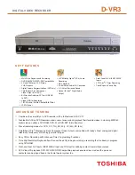
D-VR3
Brand: Toshiba Pages: 2

D-VR3SG
Brand: Toshiba Pages: 56

DVR20KB
Brand: Toshiba Pages: 80

D-VR3
Brand: Toshiba Pages: 60


