Toshiba B-EX4 T1 Series, Owner'S Manual
The Toshiba B-EX4 T1 Series is a powerful and reliable label printer that offers exceptional performance and accuracy. Get the most out of your printer by downloading the comprehensive Owner's Manual, providing step-by-step instructions and troubleshooting tips. Visit our website today to download this manual for free and unlock the full potential of your Toshiba B-EX4 T1 Series printer.
Share
Download


Reviews:
No comments
Related manuals for B-EX4 T1 Series

4800p
Brand: Hand Held Products Pages: 20

GV Series
Brand: Queclink Pages: 10

N4000
Brand: Facit Pages: 51

DB-6023
Brand: D'Tech Pages: 3

ARE i2-LF
Brand: AEG Pages: 39

ARE H9
Brand: AEG Pages: 36
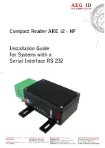
ARE i2 - HF
Brand: AEG Pages: 50
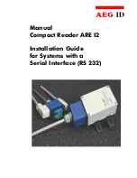
ARE I2
Brand: AEG Pages: 33

KP-2004
Brand: Toshiba Pages: 20

FCREADMINI
Brand: StarTech.com Pages: 9

MS842RP
Brand: Unitech Pages: 2

ID-80
Brand: Di-soric Pages: 14

CameraConnect Pro
Brand: ActionTec Pages: 33

MS240
Brand: Unitech Pages: 1

Basic 3
Brand: Pocketbook Pages: 70

iDC9600C
Brand: RIOTEC Pages: 7

iDC9272A
Brand: RIOTEC Pages: 5

iDC92700
Brand: RIOTEC Pages: 6


