


Part No. 08164SL (Rev. A)
Service Manual
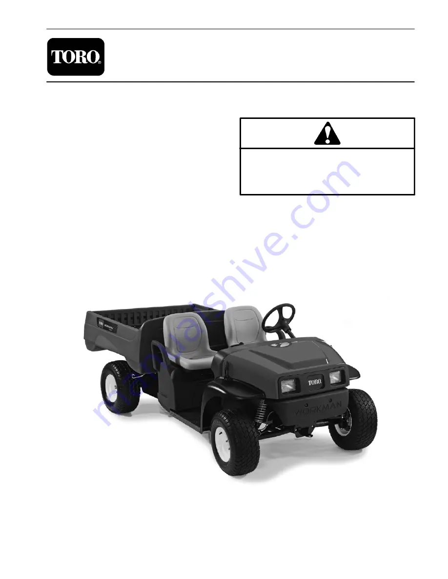
Workman
R
MDE
Preface
The purpose of this publication is to provide the service
technician with information for troubleshooting, testing
and repair of major systems and components on the
Workman MDE.
REFER TO THE OPERATOR’S MANUAL FOR OPER-
ATING, MAINTENANCE AND ADJUSTMENT IN-
STRUCTIONS. For reference, insert a copy of the
Operator’s Manual and Parts Catalog for your machine
into Chapter 2 of this service manual. Additional copies
of the Operator’s Manual and Parts Catalog are avail-
able on the internet at www.Toro.com.
The Toro Company reserves the right to change product
specifications or this publication without notice.
This safety symbol means DANGER, WARNING
or CAUTION, PERSONAL SAFETY INSTRUC-
TION. When you see this symbol, carefully read
the instructions that follow. Failure to obey the
instructions may result in personal injury.
NOTE: A NOTE will give general information about the
correct operation, maintenance, service, testing or re-
pair of the machine.
IMPORTANT: The IMPORTANT notice will give im-
portant instructions which must be followed to pre-
vent damage to systems or components on the
machine.
E
The Toro Company -- 2008, 2011
Summary of Contents for Workman MDE 2008
Page 2: ...Workman MDE This page is intentionally blank...
Page 4: ...Workman MDE This page is intentionally blank...
Page 10: ...Workman MDE Page 1 6 Safety This page is intentionally blank...
Page 12: ...0 09375 Workman MDE Page 2 2 Product Records and Maintenance Equivalents and Conversions...
Page 30: ...Workman MDE Electrical System Page 3 This page is intentionally blank Rev A 12 2...
Page 55: ...Workman MDE Page 3 37 Electrical System This page is intentionally blank Electrical System...
Page 112: ...Workman MDE Page 5 26 Chassis This page is intentionally blank Rev A...
Page 114: ...Workman MDE Electrical Diagrams Page 6 2 This page is intentionally blank...
Page 118: ...Rev A Page 6 7 This page is intentionally blank...
Page 119: ...Rev A Page 6 8 Electrical Harness Drawing Serial Number Below 310000000 Workman MDE...
Page 121: ...Rev A Page 6 10 Electrical Harness Drawing Serial Number Above 310000000 Workman MDE...
Page 123: ...Rev A Page 6 12 This page is intentionally blank...
Page 125: ...Rev A Page 6 7 This page is intentionally blank...
Page 126: ...Rev A Page 6 8 Electrical Harness Drawing Serial Number Below 310000000 Workman MDE...
Page 128: ...Rev A Page 6 10 Electrical Harness Drawing Serial Number Above 310000000 Workman MDE...
Page 130: ...Rev A Page 6 12 This page is intentionally blank...


