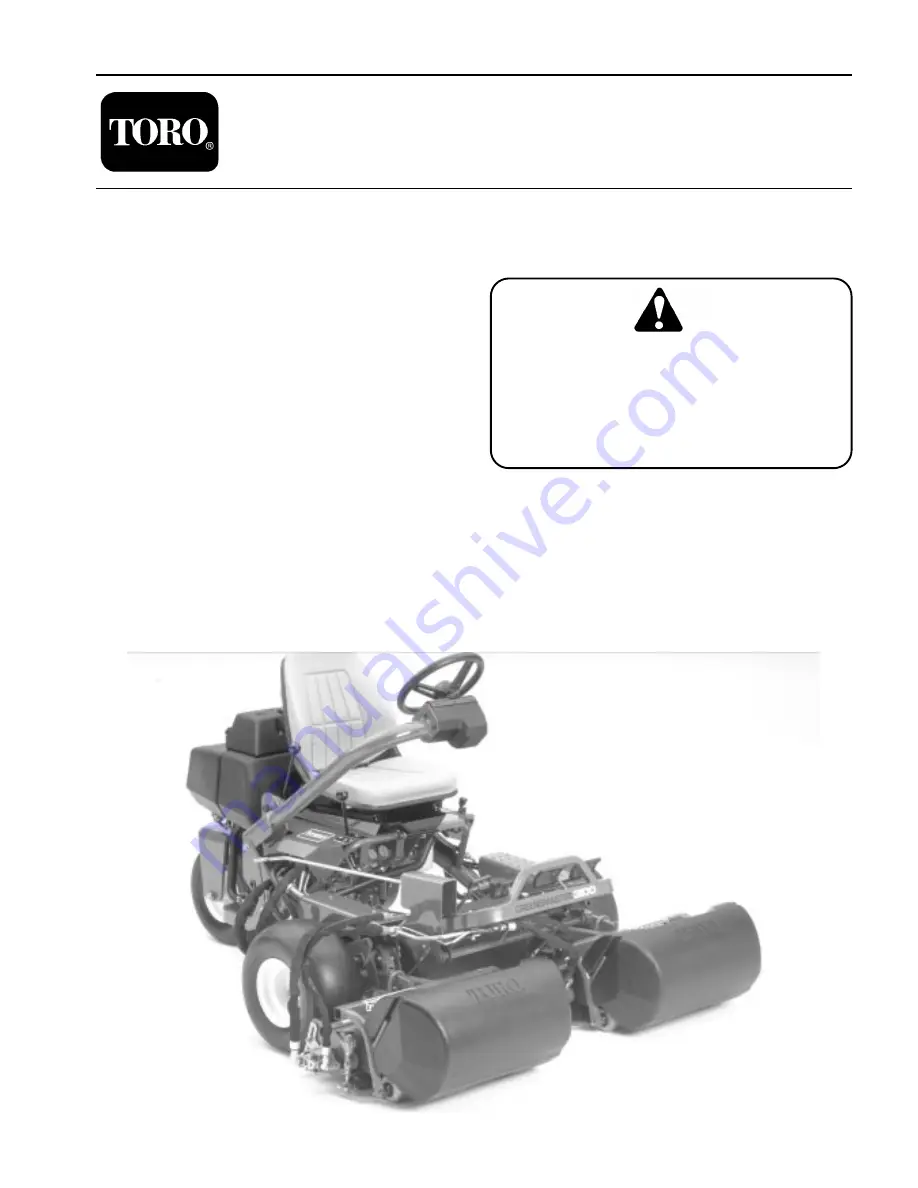
background image

Service Manual

Greensmaster

 ®

 3100/3050

Preface

This publication provides the service technician with
information for troubleshooting, testing, and repair of
m a j o r   s y s t e m s   a n d   c o m p o n e n t s   o n   t h e
Greensmaster 3100 and 3050.

REFER TO THE TRACTION UNIT, CUTTING UNIT
AND ACCESSORY OPERATOR’S MANUALS FOR
OPERATING, MAINTENANCE AND ADJUSTMENT
INSTRUCTIONS.         Space is provided at the end
of Chapter 2 in this publication to insert the Operator’s
Manuals and Parts Catalogs for your machine. Replace-
ment Operator’s Manuals are available by sending com-
plete Model and Serial Number of traction unit and
cutting unit to:

The Toro Company
8111 Lyndale Avenue South
Minneapolis, MN  55420

The Toro Company reserves the right to change product
specifications or this publication without notice. 

This safety symbol means DANGER, WARN-
ING, or CAUTION, PERSONAL SAFETY IN-
STRUCTION. When you see this symbol,
carefully read the instructions that follow.
Failure to obey the instructions may result in
personal injury.

NOTE: A NOTE will give general information about the
correct operation, maintenance, service, testing or re-
pair of the machine.

IMPORTANT: The IMPORTANT notice will give im-
portant instructions which must be followed to pre-
vent damage to systems or components on the
machine.

©

 The Toro Company - 1991, 1998

, 2002

, 200

4, 2005

Part No. 92784SL, Rev. 

E

Summary of Contents for GREENSMASTER 3100

Page 1: ... Number of traction unit and cutting unit to The Toro Company 8111 Lyndale Avenue South Minneapolis MN 55420 The Toro Company reserves the right to change product specifications or this publication without notice This safety symbol means DANGER WARN ING or CAUTION PERSONAL SAFETY IN STRUCTION When you see this symbol carefully read the instructions that follow Failure to obey the instructions may ...

Page 2: ...This page is intentionally blank ...

Page 3: ...r 5 Electrical System Wiring Schematic 5 2 Turf Guardian Leak Detection System 5 3 Special Tools 5 4 Troubleshooting 5 6 Testing 5 9 Repairs 5 13 Chapter 6 Wheels Steering and Brakes Specifications 6 2 Adjustments 6 3 Repairs 6 4 Chapter 7 4 Bolt Adjust Cutting Units Specifications 7 2 Special Tools 7 3 Troubleshooting 7 5 Set Up and Adjustments 7 7 Repairs 7 15 Chapter 8 Single Point Adjust Cutti...

Page 4: ...This page is intentionally blank ...

Page 5: ...ting maintaining or repairing the ma chine Replacement Operator s Manuals are available by sending complete Model and Serial Number of trac tion unit and cutting units to The Toro Company 8111 Lyndale Avenue South Minneapolis MN 55420 Use the Model and Serial Number when referring to your machine If you have questions about this Service Infor mation please contact The Toro Company Commercial Servi...

Page 6: ...away from moving parts and the reels The grass baskets must be in place during operation of the reels or thatchers for maximum safety Shut the engine off before emptying the baskets 16 Raise cutting units when driving from one work area to another 17 Do not touch engine muffler or exhaust pipe while engine is running or soon after it is stopped These areas could be hot enough to cause burns 18 Sta...

Page 7: ...n inspec tion or procedure use extreme caution Always use two people with the operator at the controls able to see the person doing the inspection or procedure Keep hands feet clothing and body away from cutting units and other moving parts 33 Do not overspeed the engine by changing governor settings Maximum governed engine speed should be 2850 rpm 34 Shut engine off before checking or adding oil ...

Page 8: ...Safety Instructions Page 1 4 Greensmaster 3100 ...

Page 9: ... and Torque Values Metric 3 Product Records Rev B Greensmaster 3100 Page 2 1 Product Records Insert Operator s Manual and Parts Catalog for your Greensmaster 3100 or 3050 at the end of this chapter Refer to Operator s Manual for recommended maintenance intervals Additionally insert Installation Instructions Operator s Manuals and Parts Catalogs for any accessories that have been installed on your ...

Page 10: ...___________________________________________________________________________________ To Convert Into Multiply By ___________________________________________________________________________________________________ Linear Miles Kilometers 1 609 Measurement Yards Meters 0 9144 Feet Meters 0 3048 Feet Centimeters 30 48 Inches Meters 0 0254 Inches Centimeters 2 54 Inches Millimeters 25 4 _______________...

Page 11: ...40 325 190 255 340 460 270 365 16 270 365 210 285 380 515 300 410 ________________________________________________________________________________________________________________________________________________________ 7 8 9 360 490 280 380 550 745 440 600 14 390 530 310 420 610 825 490 660 ____________________________________________________________________________________________________________...

Page 12: ...This page is intentionally blank ...

Page 13: ...________________________________________ Crankcase Oil Capacity See Operator s Manual ________________________________________________________________________________________________________________________________________________________ Oil See Operator s Manual _______________________________________________________________________________________________________________________________________...

Page 14: ...f swivel con tacts stop 4 Tighten cable clamp screw Figure 1 1 Throttle casing clamp screw 2 Throttle cable 3 Swivel 4 Stop 5 Choke casing clamp screw 6 Choke cable 7 Choke butterfly Choke Control Adjustment Fig 1 1 Loosen cable clamp screw securing cable to engine 2 Move remote choke control lever forward to CLOSED position 3 Pull firmly on choke cable until choke butterfly is completely closed t...

Page 15: ...governor lever bolt and nut to 70 in lb Throttle Restrictor Adjustment Fig 3 Move throttle control lever to SLOW position Hold governor lever so that throttle lever touches idle speed adjustment screw Use tang bender Briggs Stratton Tool 19352 and bend throttle restrictor tang so throttle opening is limited to 1 4 in travel when governor lever is released Secondary Spring Adjustments Fig 4 With th...

Page 16: ...with a tachometer 3 Adjust idle mixture screw A Turn idle mixture screw slowly clockwise lean mixture until engine speed just starts to decrease Note position of screw B Now turn idle mixture screw slowly counterclock wise rich mixture until engine speed just starts to decrease Note position of screw C Set the idle mixture screw half way between the rich and lean settings 4 After idle mixture has ...

Page 17: ...ump mount DO NOT discon nect the hydraulic hoses from the pump 6 Support the engine and remove the engine mount bolts nuts and washers to remove the engine Installing the Engine 1 Support the engine align it with the engine mounts and instal the pump hub over the engine shaft and key Be sure that the key is properly positioned and aligned with the keyway 2 Install the engine mount bolts washers an...

Page 18: ...Engine Removal and Installation Page 3 6 Greensmaster 3100 ...

Page 19: ...Hook Up No 1 Traction Pump Flow and Traction Relief Setting 28 Test Hook Up No 2 Traction Motors Mechanical Drag Valve Bank Leakage Traction Motors Efficiency 28 Test Hook Up No 3 Reel Drive Pump Efficiency 32 Test Hook Up No 4 Reel Drive Motor Flow Reel Drive Relief Setting Reel Motor Efficiency 33 Test Hook Up No 5 Steering Pump Flow and Steering Pump Relief Setting 35 ADJUSTMENTS 36 Lift and Mo...

Page 20: ...section port relief pressure 2000 psi No 2 and 3 section port relief pressure 2000 psi No 4 traction section port relief pressure 1850 psi ________________________________________________________________________________________________________________________________________________________ Power Steering Control Gerotor type steering control unit __________________________________________________...

Page 21: ...ardboard not hands to search for leaks Hydraulic fluid escaping under pressure can have sufficient force to penetrate the skin and do serious damage If fluid is injected into the skin it must be surgically removed within a few hours by a doctor familiar with this type of injury or gangrene may result Hydraulic Fitting Installation O Ring Face Seal Fig 1 2 1 Make sure both threads and sealing surfa...

Page 22: ... foreign material 2 Always replace the O ring seal when this type of fitting shows signs of leakage 3 Lubricate the O ring with a light coating of oil 4 Turn back the jam nut as far as possible Make sure the back up washer is not loose and is pushed up as far as possible Step 1 5 Install the fitting into the port and tighten finger tight until the washer contacts the face of the port Step 2 6 To p...

Page 23: ...to valve Traction lever when located in No 1 positions spool so oil is directed to flow into the No 5 metering valve section When the traction pedal is pushed forward oil flows out lines at rear of metering valve section to each motor to drive the motors Low pressure oil returns to valve through valve and main return line through filter to reservoir Greensmaster 3100 Page 4 5 Hydraulic Flow Diagra...

Page 24: ...om one pump section passes through same lines as for No 1 traction position This flow is joined by additional flow from two other pump sections The additional flow in creases the RPM of the wheel motors to increase ground speed Hydraulic Flow Diagrams Page 4 6 Greensmaster 3100 ...

Page 25: ...dal is pushed rearward flow from one pump section goes through No 4 selector valve section into No 5 metering section and out the lines at the front of the valve to the traction motors which drive the traction wheels to operate in reverse Greensmaster 3100 Page 4 7 Hydraulic Flow Diagrams ...

Page 26: ...on and out a line to right front cutting unit motor Return oil from two front cutting units joins to gether and returns to right end of valve section where is passes into the main return line and flows back to reservoir Flow from another separate pump section passes through No 3 spool section and out through a line to the rear cutting unit drive motor Return oil from the motor passes through a lin...

Page 27: ...inders and lowers the cutting units Oil is returned to a three way fitting on the No 1 spool section through lines on the top end of each cylinder where it passes through the valve section and returns to the reservoir through the main return line When the cylinders complete their travel oil flow from the No 3 spool section is then directed to the rear cutting unit drive motor Greensmaster 3100 Pag...

Page 28: ...pools fully in This directs flow from one pump section to pass through end cover and No 1 spool valve out three lines leading to lift cylinders causing cylinders to raise the cutting units Oil forced out of cylinders travels through lines leading to No 3 spool section through the valve bank and back to reservoir through main re turn line Hydraulic Flow Diagrams Page 4 10 Greensmaster 3100 ...

Page 29: ...wheel turns system oil is metered out port R to the steering cylinder Oil displaced by the other end of the steering cylinder returns to the steering valve through port L which directs it out port T back to reservoir When the steering wheel stops turning the control sec tion within the steering valve shifts back to neutral allowing all oil from the pump to flow through the steering valve out port ...

Page 30: ...L VALVE 4 5 CU IN REV 75 CU CM REV 2000 PSI 141 KG SQ CM 2000 PSI 141 KG SQ CM 2000 PSI 141 KG SQ CM 1850 PSI 130 KG SQ CM 2ND 1ST N FWD N REV 3 58 IN REV 9 5 CU CM REV 3 33 IN REV 5 4 CU CM REV 850 PSI 60 KG SQ CM 2 9 CU CM REV 3 18 IN REV SAFETY INTERLOCK SWITCH 3 33 IN REV 5 4 CU CM REV 2850 RPM MAX OIL FILTER 10 MICRON LEVEL SENSOR HYDRAULIC TANK NORMALLY OPEN SOLENOID VALVE AUXILIARY HYDRAULI...

Page 31: ...EERING CONTROL VALVE 4 5 CU IN REV 75 CU CM REV 2000 PSI 141 KG SQ CM 2000 PSI 141 KG SQ CM 2000 PSI 141 KG SQ CM 1850 PSI 130 KG SQ CM 2ND 1ST N FWD N REV 3 57 IN REV 9 3 CU CM REV 3 32 IN REV 5 2 CU CM REV 850 PSI 60 KG SQ CM 2 9 CU CM REV 3 18 IN REV SAFETY INTERLOCK SWITCH 2850 RPM MAX OIL FILTER 10 MICRON LEVEL SENSOR HYDRAULIC TANK NORMALLY OPEN SOLENOID VALVE AUXILIARY HYDRAULIC TANK BREATH...

Page 32: ...STEERING CYLINDER L R P T SAFETY INTERLOCK SWITCH SAFETY INTERLOCK SWITCH 2ND 1ST N N FWD REV 1850 PSI 130 KG SQ CM LH RH WHEEL DRIVE MOTORS 10 3 CU IN REV 169 CU CM REV LEVEL SENSOR HYDRAULIC TANK VALVE OIL FILTER 10 MICRON WHEEL DRIVE MOTOR 20 CU IN REV 328 CU CM REV TANK BREATHER 40 MICRON AUXILIARY HYDRAULIC TANK 33 IN REV 5 4 CU CM REV 33 IN REV 5 4 CU CM REV PUMP DANFOSS 2850 RPM MAX 58 IN R...

Page 33: ...H WHEEL DRIVE MOTORS 10 3 CU IN REV 169 CU CM REV 2000 PSI 141 KG SQ CM 2000 PSI 141 KG SQ CM 2000 PSI 141 KG SQ CM 1850 PSI 130 KG SQ CM 2ND 1ST N FWD N REV 3 33 IN REV 5 4 CU CM REV SAFETY INTERLOCK SWITCH 3 33 IN REV 5 4 CU CM REV 2850 RPM MAX 43 CU IN REV 7 CU CM REV VALVE BANK SAFETY INTERLOCK SWITCH 3 58 IN REV 9 5 CU CM REV HYDRAULIC TANK OIL FILTER ...

Page 34: ...Greensmaster 3100 Page 4 12 4 Hydraulic Schematics Rev E This page is blank ...

Page 35: ...Low range gauge to provide accurate reading at low pressure 0 1000 psi 0 6895 kPa This gauge has a protector valve which cuts out when pressure is about to exceed the normal range for the gauge The cutout pressure is adjustable 4 HIGH PRESSURE GAUGE High range gauge to accommodate pressure beyond the capacity of the low pressure gauge 0 5000 0 34475 kPa 5 FLOW METER This meter measures actual oil ...

Page 36: ...Use the installer Item 2 and a small hammer to drive the reel motor shaft seal into position in the bore of the reel motor body Figure 7 Detent Installation Tool Fig 8 Use this tool with a 3 8 in drive torque wrench to tighten the detent stud in the No 1 spool of the control valve Apply Loctite 222 or equivalent to the threads of the detent stud Tighten the stud to a torque of 10 14 ft lb Figure 8...

Page 37: ...or IMPORTANT The wheel motor geroters are indexed and must be kept in their original position Figure 10 Control Valve Spool Seal Installation Tools Fig 11 This tool can be made to the dimensions shown Soak new seal in clean hydraulic fluid before installing Install seal into end of large diameter tool with open side of seal facing out Install small diameter tool into large diameter tool against fl...

Page 38: ...ause of the trouble and correct it before allowing the machine to be used again Continued use of an improperly functioning hydraulic system could lead to extensive internal component damage The charts that follow contain detailed information to assist in troubleshooting There may possibly be more than one cause for a machine malfunction All causes should be checked in the order in which they are l...

Page 39: ...ck traction relief Test hook up No 1 Test B Repair or replace pump Repair or replace defective motor Check traction pump flow Test hook up No 1 Test A Free linkage and adjust brakes Check traction mo tor efficiency Test hook up No 2 Test C Repair or replace defective motor OK Improper OK Clogged OK Binding OK Defective OK OK Inefficient OK Check traction mo tors for mech drag Test hook up No 2 Tes...

Page 40: ...on pump flow Test hook up No 1 Test A Remove valve bank and replace disk seal Repair or replace traction pump Check for internal valve bank leakage Test hook up No 2 Test B Check disk seal between 3 and 4 valve sections Check control linkage Leaking OK Check for restriction in pump intake line Troubleshooting Page 4 18 Greensmaster 3100 ...

Page 41: ... and 3 valve section re liefs Test hook up No 4 Test B Adjust or repair Check hydraulic oil level Repair or replace relief valve Adjust or repair OK Check traction lever Check rear camshaft Defective Check 2 and 3 pump section flow Test hook up No 3 Test A OK Repair or replace pump Check for restriction in pump intake line Greensmaster 3100 Page 4 19 Troubleshooting ...

Page 42: ...fe Repair or replace reel drive relief valve OK Check reel motor flow Test hook up No 4 Test A Check rear ward valve spool trave Repair or replace pump Check for tight reel bearings Adjust bearings Replace if necessary OK Tight OK OK OK Check reel drive relief Test hook up No 4 Test B Repair or replace reel drive motor OK Check reel motor efficiency Test hook up No 4 Test B Low Check for restricti...

Page 43: ...l to proper level Check reel pump flow Test hook up No 3 Test A Check hydraulic oil filter Replace filter Check hydraulic oil level Check linkage and roll pin on end of mow pedal shaft Repair linkage OK Worn or broken OK OK Low Repair or replace pump Greensmaster 3100 Page 4 21 Troubleshooting ...

Page 44: ...K Adjust repair and lubricate linkage Check linkage from pedal to valve bank Replace pin Check rearward valve spool travel Adjust rear camshaft Check roll pin in end of mow pedal shaft Check the spool detent Lubricate or repair valve spool detent Defective OK OK Troubleshooting Page 4 22 Greensmaster 3100 ...

Page 45: ...hat valve spool returns to neutral Repair or replace cylinder s Check lift check plug o rings in 1 valve section Replace o ring Check for internal lift cylinder leakage Check valve spool detent for binding Lubricate or repair valve spool detent Binding OK OK Greensmaster 3100 Page 4 23 Troubleshooting ...

Page 46: ...blies Adjust rear camshaft Check lift section of pump Test hook up No 3 Test A Check for restriction in lines to or from cylinders Replace restricted line or fitting Check forward valve spool travel Check for leaking cylinder Repair or replace cylinder OK Leaking OK OK Defective Repair or replace pump Troubleshooting Page 4 24 Greensmaster 3100 ...

Page 47: ...n Check for restriction in valve return port between 3 section and R H cover Remove valve bank and disassemle to remove restriction Check for restric tion in brazed tube assembly on 3 valve section OK Center 1 Cutting Unit Drops Before Front Cutting Units or Drops Too Fast Incorrect Missing OK Install orifice re ducer in cylinder line Check for missing orifce reducer in cylin der line attached to ...

Page 48: ...d steering control unit Thermal shock Defective Repair or replace steering control unit OK Defective OK OK Repair or replace pump Check steering pump flow Test hook up No 5 Test A Tighten castle nuts and jam nut Thermal shock A condition caused when the hydraulic system is operated for some time without turning the steering wheel so that fluid in the reservoir and system is hot and the steering co...

Page 49: ...e Performing Hydraulic Tests 1 Thorough clean the machine before disconnecting or disassembling any hydraulic components Always keep in mind the need for cleanliness when working on hy draulic equipment 2 Put caps or plugs on any hydraulic lines left open or exposed during testing or removal of components 3 The engine must be in good operating condition ALWAYS use a tachometer when making a hydrau...

Page 50: ...engine when the traction lever is engaged TEST A TRACTION PUMP FLOW PROCEDURE Traction lever in neutral Engine RPM 2800 RPM Hydraulic oil at operating temperature While watching flow and pressure gauges slowly close flow control valve until 1000 PSI is obtained TESTER READINGS Flow not lower than 5 GPM at 1000 PSI Record pressure and flow readings If flow is lower than 5 GPM or a pressure of 1000 ...

Page 51: ...d engage park lock Engine RPM 2800 Hydraulic oil at normal operating temperature Engage transmission lever to No 1 position Push traction pedal to forward position TESTER READINGS Pressure 1850 to 1950 PSI If pressure is not in listed range remove traction relief cartridge and examine for contamination or damage Greensmaster 3100 Page 4 29 Testing ...

Page 52: ...tall tester in series between the two exposed fittings CAUTION Keep everyone away from the front of the machine during traction system tests Op erator must be on seat or the safety interlock will stop the engine when the traction lever is en gaged 1 TESTER 2 3 4 5 CAP TEST B AND C CAP TEST B AND C TEST A TRACTION MOTORS MECHANICAL DRAG PROCEDURE Block up the machine so traction wheels are off floo...

Page 53: ...uges slowly close flow control valve until 1000 PSI is obtained TESTER READINGS Flow not less than 5 GPM at minimum 1000 PSI If flow is lower than 5 GPM or pressure of 1000 PSI cannot be obtained there is internal valve bank leakage Check 1 Relief valve 2 No 4 spool position 3 Disc seal between No 3 and No 4 valve bank sections TEST C TRACTION MOTOR EFFICIENCY PROCEDURE Tester Flow Control Valve O...

Page 54: ...n seat or the safety interlock will stop the engine when the mow pedal is engaged TEST A REEL DRIVE PUMP EFFICIENCY PROCEDURE Traction lever in neutral position Engine RPM 2800 Hydraulic oil at operating temperature While watching pressure gauges slowly close flow control valve until 1000 PSI is obtained Read flow gauge TESTER READINGS Flow not less than 2 5 GPM at 1000 PSI If unable to get 1000 P...

Page 55: ...eat or the safety interlock will stop the engine when the mow pedal is engaged TEST A REEL DRIVE MOTOR FLOW PROCEDURE Engine RPM 2800 Mow pedal engaged While watching pressure gauges slowly close flow control valve until 1000 PSI is obtained Read flow gauge TESTER READINGS Flow not less than 2 5 GPM at 1000 PSI If unable to get 1000 PSI or flow is below 2 5 GPM check rearward spool travel If spool...

Page 56: ...e to prevent reel from turning Engine RPM 2800 Hydraulic oil at operating temperature Engage mow pedal TESTER READINGS Flow not more than 0 5 GPM at 2000 to 2100 PSI If flow is above 0 5 GPM remove motor and repair as necessary If pressure is is not in listed range remove relief valve controlling reel being checked and examine for wear or contamination Testing Page 4 34 Greensmaster 3100 ...

Page 57: ...action Lever in neutral Engine RPM 2800 Hydraulic oil at operating temperature While watching flow and pressure gauges slowly close flow control valve until 600 PSI is obtained TESTER READINGS Flow not lower than 1 5 GPM at 750 to 850 PSI If flow is less than 1 5 GPM check for restriction in pump intake line If not restricted remove pump and repair as necessary If pressure not within listed range ...

Page 58: ...otter pin and clevis pin 3 Move adjustment lever by hand to level the mow and lift pedals and adjust yoke on control rod until hole in yoke lines up with the adjustment lever hole 4 Install the clevis pin and cotter pin tighten the jam nut and install the transfer rod guard 5 Actuate the mow pedal by hand Be sure the lift pivot under the pedals clears the stop welded to the frame thereby allowing ...

Page 59: ... completely out or if pedal does not make contact with stop an adjustment to the stop is necessary 3 Loosen hex nut securing threaded rod to frame Turn flange nut on rod to raise or lower stop rod while checking pedal 4 When completed retighten nut Figure 14 1 Fully forward 3 Reverse 2 Pedal stop 4 Control rod Traction Return Linkage Fig 14a If shift selector does not return to Neutral or No 1 pos...

Page 60: ...or more malfunctions occur loosen the rear camshaft mounting capscrews and relocate the cam shaft until the condition is corrected Retighten the capscrews You must readjust the mow lift switch when the camshaft adjustment is completed See Mow Lift Switch Adjustment in the Adjust ments section of Chapter 5 Electrical Sys tem The lift and mow pedal height must also be adjusted See Lift and Mow Pedal...

Page 61: ...ll motor out 4 Remove snap ring from motor 5 Start the engine DO NOT engage the mow pedal Back pressure in the hydraulic system will push shaft seal out of motor Stop the engine NOTE Seal may also be removed by punching two holes in face of seal 180o apart installing metal screws and pulling seal out by grasping the screws 6 Disconnect hydraulic lines from motor 7 Remove and discard shaft seal and...

Page 62: ...NOTto remove the bearing races from the cover and body 7 Remove and discard the bridging insert gasket in sert anti extrusion block snap ring shaft seal spacer seal assembly wear plate and o ring Items 5 6 8 11 14 15 and 17 These items are available in a repair kit 8 Clean all parts and check for burrs scoring nicks etc 9 Rub mating surfaces of body and cover with 400 grit or finer sandpaper to re...

Page 63: ...7 Assemble the body to the cover making sure that none of the parts become displaced Insert the cap screws and washers and hand tighten 18 Before tightening the capscrews rotate the drive shaft in the direction of normal rotation counterclock wise to check for binding You may not be able to rotate the drive shaft by hand Protect the shaft if using a pliers 19 Tighten the capscrews evenly in a cros...

Page 64: ...IMPORTANT To prevent damage to load plate or cover during motor operation do not mark gears with a punch or scribe 6 Be careful when disassembling The needle bearings 5 may be of the loose grease retained type Pack these with general purpose grease to retain them for re asembly It is recommended NOT to remove the bearing races from the cover and body 7 Remove the load plate assembly 9 8 Remove and...

Page 65: ...rclock wise to check for binding You may not be able to rotate the drive shaft by hand Protect the shaft if using a pliers 16 Tighten the capscrews evenly in a crossing pattern to a torque of 17 ft lb 17 Carefully install a new spacer shaft seal and snap ring Perform steps 8 12 under Reel Motor Shaft Seal Replacement in this section of the book ...

Page 66: ...10 Cap screw 11 Front flange Figure 18b 7 4 3 1 2 5 6 9 10 11 45 to 55 Nm 33 to 40 ft lb 8 5 6 7 Disassembly 1 Plug motor ports and clean the outside of the motor thoroughly After cleaning remove plugs and drain any oil out of the motor 2 Use a marker or scribe to make a diagonal mark across the front flange body and rear cover for reas sembly purposes Fig 18c Figure 18c DIAGONAL MARK ...

Page 67: ...r finish 7 Place the motor on its side and push on the rear bear ing block to remove the bearing block and gear set Fig 18d 8 Carefully remove and discard o rings pressure seals and back up rings Fig 18e from motor Do not cause any damage to the machined grooves during the removal process IMPORTANT Make sure not to damage the counter bore when removing the shaft seal from the front plate 9 Positio...

Page 68: ... back up rings into the grooves 4 Install new o rings to the body 5 Lubricate gear faces and bearing surfaces of drive gear idler gear and bearing blocks Carefully assemble bearing blocks and gears noting identification marks made during disassembly 6 Position the motor body on its side Carefully slide bearing block and gear assembly into the body cavity using identification marks made during disa...

Page 69: ...This page is intentionally blank ...

Page 70: ...lines clean and free from debris During replacement avoid overtightening fittings see the Hydraulic Hose and Fitting Information section of this chapter Check hydraulic lines for breaks or cracks Check the hydraulic reservoir for proper fluid level after replacement of any large component 3 Loosen the set screws Item 13 securing the pump hub Item 22 to the shaft remove the capscrews Item 24 mounti...

Page 71: ... Up No 5 Steering Pump Flow and Steering Pump Relief Set ting in the Testing section of this chapter Pump Service 1 Plug ports and wash exterior of pump with mineral spirits or solvent Make sure parts and work area are clean 2 Draw a line across the seam areas on the pump case with a scribe or marker to ensure proper reassembly IMPORTANT Use caution when using a vise to avoid distorting any parts ...

Page 72: ...plates Items 14 25 and 30 and insert gear sets maintaining the original timing and locations 11 Assemble pump sections starting at the body as sembly Item 15 Install woodruff keys Item 19 and align keyways in gears as they are installed over the shafts Apply grease to new seal rings Item 23 before installing 12 After pump has been assembled tighten locknuts by hand Rotate the drive shaft to check ...

Page 73: ...nes and Fittings section of this chapter 7 Check to be sure all lines are routed correctly and are not in contact with one another or other components It should be possible to slip a strip of paper between any lines and other components in close relationship Relo cate if necessary 8 Adjust the traction linkage switches and reel drive camshaft as necessary Figure 23 Relief Valve Removal and Install...

Page 74: ...he bonnet on No 4 spool 2 Disassemble the components attached to the rear of the spool See Control Valve No 1 Spool Detent Re placement and Control Valve No 4 Spool Detent Re placement in this section of the book NOTE The assemblies under each spool bonnet are different from one another Pay close attention to how they are disassembled so they will be reassembled correctly 3 Remove the seal retaine...

Page 75: ...together Fig 27 3 Slide each section off the studs Identify them so they will not be reassembled in the wrong location 4 Remove all original o ring seals clean the o ring grooves and check the mating surfaces of each section for any imperfections or contaminants which could cause leakage to occur 5 Soak the replacement o rings in clean hydraulic fluid and install them into the ring grooves as you ...

Page 76: ... in 6 mm of 2 multi purpose Lithium base grease on top of thick washer Item 5 5 Install twelve balls Item 4 into thrust plate Item 5 IMPORTANT If the detent bonnet contains a vent pocket do not let the balls fall into the vent 6 Insert race Item 3 on top of balls with ramp of race facing inward as shown Rotate race Item 3 until you are sure all balls are resting properly against the sur faces of t...

Page 77: ...res 1 Mount the detent sleeve and the detent adapter Lock the adapter securely to the spool 2 Apply a light coat of grease to the adapter holes insert the small spring the four balls and the ball follower 3 Stand the valve bank assembly up so the front clevis end of No 4 spool is facing downward 4 Slide the detent sleeve up to the four balls Apply light pressure against the balls with the sleeve P...

Page 78: ...on of lift arm in cylinder clevis before reinstalling IMPORTANT When disassembling hydraulic lines make sure hydraulic plugs are placed in the open end of the hydraulic line to prevent foreign debris from contaminating hydraulic oil It is also a good idea to tag the hydraulic lines when disassembling so they can be properly reassembled Keep all hy draulic lines clean and free from foreign debris D...

Page 79: ...chieve free pivot action of the cylinder before reassembling IMPORTANT When disassembling hydraulic lines make sure hydraulic plugs are placed in the open end of the hydraulic line to prevent foreign debris from contaminating hydraulic oil It is also a good idea to tag the hydraulic lines when disassembling so they can be properly reassembled Keep all hy draulic lines clean and free from foreign d...

Page 80: ...n a vise and remove the lock nut Item 2 from the piston end of the shaft Remove the piston Item 4 Slide the head Item 8 off of the shaft 6 Remove and discard all seals and back up rings Items 3 5 6 7 9 7 Wash the parts in a safe solvent Dry the parts with compressed air DO NOT wipe them dry with a cloth or paper as lint and dirt may remain 8 Inspect the internal surface of the barrel Item 1 for da...

Page 81: ...t the shaft Item 6 in a vise and remove the lock nut Item 2 from the piston end of the shaft Remove the piston Item 3 Slide the head Item 9 off of the shaft 6 Remove and discard all seals and back up rings Items 4 5 12 7 8 11 7 Wash the parts in a safe solvent Dry the parts with compressed air DO NOT wipe them dry with a cloth or paper as lint and dirt may remain 8 Inspect the internal surface of ...

Page 82: ...tem 9 and lock nuts Item 19 to remove wheel motor Item 22 and brake brackets Item 12 from frame 6 Reverse steps 1 6 to install the wheel motor Tighten nut Item 4 to a torque of 250 400 ft lb IMPORTANT When disassembling hydraulic lines make sure hydraulic plugs are placed in the open end of the hydraulic line to prevent foreign debris from contaminating hydraulic oil It is also a good idea to tag ...

Page 83: ...utator seal Item 15 from commutator Item 16 using an air hose to blow air into ring groove until seal ring is lifted out and discard seal Inspect commutator and commutator ring for cracks or burrs Inspect commutator for wear scoring spalling or brinelling If any of these conditions exist replace com mutator and commutator ring as a matched set 7 Remove manifold Item 22 Inspect manifold for cracks ...

Page 84: ...t be firmly retained in the bearing cages but must rotate and orbit freely All rollers and the thrust washers must be free of brinelling and corrosion Before Assembling Motor Replace all seals and seal rings with new ones Lubri cate all seals and seal rings with hydraulic oil or clean grease before assembly NOTE Unless otherwise indicated do not oil or grease parts before assembly Wash all parts i...

Page 85: ...e more than 50 ft lb 68 Nm Rotor Stator and Vane Assembly Fig 37 38 1 Place stator Item 21 onto wear plate Item 18 after doing motor assembly procedures 1 through 7 2 If assembly alignment studs are not being used align stator bolt holes with wear plate bolt holes and turn two 2 bolts Item 14 finger tight into bolt holes 180 apart to keep stator and wear plate stationary 3 Assemble six vanes Item ...

Page 86: ... steps 1 3 to install the steering cylinder 5 After installing the cylinder start the engine and turn the steering wheel left and right from lock to lock several times to get air out of the cylinder IMPORTANT When disassembling hydraulic lines make sure hydraulic plugs are placed in the open end of the hydraulic line to prevent foreign debris from contaminating hydraulic oil It is also a good idea...

Page 87: ...tion to carefully remove rod assembly Item 9 and head from the barrel Remove head Item 5 from other end of barrel 6 Slide head off of rod assembly 7 Remove and discard all seals and back up rings 8 Wash parts in solvent Dry the parts with compressed air DO NOT wipe them dry with a cloth or paper as lint and dirt may remain 9 Inspect internal surface of barrel for damage deep scratches out of round...

Page 88: ... This could damage the steering valve com ponents 4 Remove four capscrews Item 7 and lower the steer ing valve Item 24 and steering column Item 23 out of the steering arm 5 Reverse steps 1 4 to install the steering valve Tighten the steering wheel nut so the top surface of the nut is flush with the top of the steering column IMPORTANT When disassembling hydraulic lines make sure hydraulic plugs ar...

Page 89: ...e 25 O ring 8 Bearing race 17 Gerotor 26 Setscrew 9 Needle thrust bearing 18 End cap Disassembly Cleanliness is extremely important when repairing a steering control unit Work in a clean area Before disconnecting lines clean port area of unit thoroughly Use a wire brush to remove foreign material and debris from around exterior joints of the unit Although not all drawings show the unit in a vise i...

Page 90: ...rea Use protective material on vise jaws Housing distortion could result if jaws are over tightened 2 Remove 5 16 cap screws 3 Remove end cap 4 Remove seal from end cap 5 Remove meter Be careful not to drop star 6 Remove seal from meter Figure 43 Figure 44 Figure 45 Repairs Page 4 62 Greensmaster 3100 ...

Page 91: ...n soft cloth to protect surface finish Use a thin blade screwdriver to pry retaining ring from housing 11 Rotate spool and sleeve until pin is horizontal Push spool and sleeve assembly forward with your thumbs just far enough to free gland bushing from housing Remove bushing Figure 46 Figure 47 Figure 48 Greensmaster 3100 Page 4 63 Repairs ...

Page 92: ...ing races and the needle thrust bearing from spool and sleeve assembly 15 Remove spool and sleeve assembly from 14 hole end of housing IMPORTANT Do not bind spool and sleeve in hous ing Rotate spool and sleeve assembly slowly when removing from housing 16 Push pin from spool and sleeve assembly Figure 49 Figure 50 Figure 51 Repairs Page 4 64 Greensmaster 3100 ...

Page 93: ...owly when removing from sleeve 19 Remove seal from housing 20 Remove set screw from housing 21 Screw a 10 24 machine screw into end of check ball seat Then by pulling on screw with a pliers lift seat out of housing 22 Remove two 2 seals from check valve seat 23 Tip housing to remove check ball and check ball retainer Figure 52 Figure 53 Greensmaster 3100 Page 4 65 Repairs ...

Page 94: ...iner is straight not tilted on edge in housing 2 Install check ball in housing 3 Lubricate 5 8 diameter seal and 7 16 diameter seal Install seals on check ball seat as shown 4 Lubricate check ball seat and seals thoroughly before installing seat in housing When installing seat do not twist or damage seals Install check ball seat in housing insert open end of seat first Push check ball seat to shou...

Page 95: ...y until pin becomes flush at both sides of sleeve 11 Position the spool and sleeve assembly so that the splined end of the spool enters the 14 hole end of housing first IMPORTANT Be extremely careful that the parts do not tilt out of position while inserting Push parts gently into place with slight rotating action keep pin nearly horizontal Bring the spool assembly entirely within the housing bore...

Page 96: ...s freely into pocket of bushing see Fig 60 16 Install seal gland bushing over the spool end with a twisting motion Tap the bushing in place with a rubber hammer Make sure the bushing is flush against the bearing race 17 Install retaining ring see Fig 59 60 in housing After installing ring tap on ring end or pry with screw driver around entire circumference of ring to properly seat ring in groove F...

Page 97: ...MPORTANT Clean the upper surface of the hous ing by wiping with the palm of clean hand Clean each of the flat surfaces of the meter section parts in a similar way when ready for reassembly Do not use cloth or paper to clean surfaces 19 Install 3 diameter seal in housing 20 Install spacer plate Align bolt holes in spacer plate with tapped holes in housing Figure 61 Figure 62 Greensmaster 3100 Page ...

Page 98: ...Note relationship between slotted end of drive to splined end of drive when mark ing 22 Install 3 diameter seal in meter 23 With seal side of meter toward spacer plate align star valleys ref A on drive ref B Note the parallel relationship of reference lines A B C and D Align bolt holes without disengaging meter from drive Figure 63 Figure 64 Figure 65 Repairs Page 4 70 Greensmaster 3100 ...

Page 99: ...l end cap on gerotor align holes 26 Install seven 7 DRY cap screws with new seal washers in end cap Pre tighten screws to 150 inch pounds then torque screws to 275 inch pounds in sequence shown Figure 66 Figure 67 Greensmaster 3100 Page 4 71 Repairs ...

Page 100: ...Repairs Page 4 72 Greensmaster 3100 ...

Page 101: ...t Switch 11 Interlock Module 11 Battery 12 Hourmeter 12 Turf GuardianTM Leak Detection System 12 REPAIRS 13 General Safety Interlock Switch Service 13 Seat Switch Replacement and Adjustment 13 Traction Neutral Switch Replacement and Adjustment 14 Mow Lift Switch Replacement and Adjustment 15 Wiring Harness Service 15 Battery Service 16 See Chapter 3 Engine for information about the engine electric...

Page 102: ...BLACK GREEN BLUE WHITE RED BLACK BLACK BLACK RED WHITE RED WHITE ORANGE RED BLACK RED WHITE RED WHITE GREY BLACK ORANGE BROWN YELLOW YELLOW GREEN RED RED BLUE WHITE RED WHITE RED WHITE RED RED WHITE ORANGE YELLOW BLUE ORANGE ORANGE RED BLACK OPTIONAL LIGHTS WHITE RED BLUE RED WHITE A B GREY GREY BLACK BROWN BROWN RESISTOR FUSE 20 AMP RED RED RED WHITE MOW SWITCH TIMER KEY POSITION CIRCUIT MADE 1 O...

Page 103: ...DLE SW V V METER GY BK GY Y GY CLOSED IN NEUTRAL CLOSED WHEN OCCUPIED W SP 10A 2 1 FUSE FL OR FUSIBLE LINK STARTER SPLICE SP Y YELLOW OR ORANGE R B FL GY GRAY R PU PURPLE RED W WHITE BK BN BU BLACK BROWN BLUE S B A Y STOP NONE RUN B I A X Y START B I S BU BN BU OR X I A X Y S I B RUN START OFF IGNITION SW CLOSED WHEN THERE S A HYDRAULIC OIL LEAK LEAK DETECTOR LIGHT TEST SW TO THE LIGHTS OPTIONAL B...

Page 104: ... ST AR TERSOLENOID MAGNETO ENGINE GND FRAME GND SP BATTERY VIO VOL T VOL T METER W BK 30 85 87 86 87a KILL RELAY CLOSED WHEN OFF MOW SW GY 30 85 87 86 87a PARKING BRAKE RELAY BK VIO D1 W GN R OR FL W SP 10A STARTER X Y A B S I OR A X Y S I B RUN ST AR T OFF IGNITION S W BN BU CLOSED WHEN THERE S LEAK DETECTOR A HYDRAULICOIL LEAK T O THE LIGHTS OPTIONAL LIGHT TEST SW SOLENOID VALVE GY BK BU GY BU T...

Page 105: ...G BRAKE SW Y BN D2 VIO BK FL STARTER SOLENOID MAGNETO ENGINE GND FRAME GND SP BATTERY VIO VOLT VOLT METER W BK 30 85 87 86 87a KILL RELAY CLOSED WHEN OFF MOW SW GY 30 85 87 86 87a PARKING BRAKE RELAY BK VIO D1 W GN R OR FL W SP 10A STARTER X Y A B S I OR A X Y S I B RUN ST ART OFF IGNITION SW BN BU TO THE LIGHTS OPTIONAL LIGHT TEST SW BU BU VIO HR HR METER SEAT SW CLOSED WHEN OCCUPIED BU BK GY STO...

Page 106: ...ACK GREEN BLUE WHITE RED BLACK BLACK RED WHITE RED WHITE ORANGE RED BLACK BLACK ORANGE BROWN YELLOW YELLOW GREEN RED RED BLUE WHITE RED WHITE RED WHITE RED RED WHITE ORANGE YELLOW BLUE ORANGE ORANGE RED BLACK OPTIONAL LIGHTS WHITE RED BLUE RED WHITE FUSE 20 AMP RED RED RED WHITE MOW SWITCH KEY POSITION CIRCUIT MADE 1 OFF G M A 2 RUN B L A 3 START B L S MODULE INTERLOCK A YELLOW ORANGE BLUE B C D E...

Page 107: ...Greensmaster 3100 3050 Page 5 2 5 Wiring Schematics Rev D Wiring Schematic Greensmaster 3050 S N 80001 200999999 ...

Page 108: ... VIO BK FL STARTER SOLENOID MAGNET O ENGINE GND FRAME GND SP BATTERY VIO VOLT VOLT METER W BK 30 85 87 86 87a KILL RELAY CLOSED WHEN OFF MOW SW GY 30 85 87 86 87a PARKING BRAKE KILL RELAY BK VIO D1 W GN R OR FL W SP 10A STARTER X Y A B S I OR A X Y S I B RUN START OFF IGNITION SW BN BU TO THE LIGHTS OPTIONAL LIGHT TEST SW BU BU VIO HR HR METER SEAT SW CLOSED WHEN OCCUPIED BU BK GY STOP NONE RUN B ...

Page 109: ...e Color Violet Magneto Connector Located on back of engine J 7 Key Switch Connector Cavity Wire 1 White 2 Violet 3 LT Blue Blue 4 Red 5 Orange Located under Control console LH side of machine P 1 Engine Ground Connector Cavity Wire A Black Located front side of engine block J 10 Mow Switch Connector Cavity Wire A Brown B Yellow Located on front LH side of Hydraulic valve P 2 Volt Meter Connector C...

Page 110: ...This page is intentionally blank ...

Page 111: ...fluid expands caus ing it to flow into overflow tank Float stays in raised position keeping alarm circuit open Leak Alert If oil leaks during operation fluid level drops in system hydraulic tank This causes float to lower closing alarm circuit After a one second delay alarm will sound NOTE During normal operation with cutting units low ered approximately 5 oz of oil will leak before float switch a...

Page 112: ...local supplier Continuity Tester Fig 5 Battery powered test lamp which is helpful in testing for continuity of circuits and electrical components when the current is off Figure 5 Volt Ohm Amp Meter Fig 6 The meter can test electrical components and circuits for current resistance or voltage draw Figure 6 Special Tools Page 5 4 Greensmaster 3100 ...

Page 113: ... 7 Special non conductive grease which forms a light pro tective skin to help waterproof electrical switches and contacts Recommended for all interlock system con nections Figure 7 Greensmaster 3100 Page 5 5 Special Tools ...

Page 114: ...gine starts but should not when shift selector is in gear Traction switch adjusted incorrectly or is malfunctioning Adjust or replace traction switch 2 Engine starts but should not when mow pedal is depressed reels engaged Mow lift switch adjusted incorrectly or is malfunctioning Adjust or replace mow lift switch 3 Engine fails to crank regard less of shift selector or mow pedal position Mow lift ...

Page 115: ... spring broken miss ing or stuck in down position Seat pivot does not rotate freely Adjust or replace traction switch or seat switch Replace loosen and lubricate parts so pin operates freely Loosen and lubricate seat pivot pin to make sure if pivots freely 8 Engine does not continue to run when sitting on seat and shift selector is placed in No 1 or No 2 position or mow pedal is pushed down Seat s...

Page 116: ...ly proceed to step 2 If the engine cranked refer to Troubleshooting in this chapter 2 Sit on the seat and engage the parking brake Push the lift pedal down all the way and release it Move the shift selector to the neutral N position and try to start the engine The engine should start and continue to run which means that the traction switch and mow lift switch is operating correctly proceed to step...

Page 117: ...the component being tested from the circuit When testing electrical components with a volt ohm meter or continuity tester make sure that power to the circuit has been dis connected Ignition Key Switch Fig 8 The ignition key switch has three positions OFF START and RUN The terminals are marked as shown The circuitry of the ignition switch is shown in the charts With the use of a continuity tester t...

Page 118: ...n switch wire connector and install a continuity tester or ohm meter between the two leads of the traction switch 2 Make sure the shift selector is in the neutral N position There should be continuity when the shift selector is in the neutral N position If there is no continuity adjust or replace the switch See Traction Neutral Switch Replacement and Adjustment in the Repairs section of this book ...

Page 119: ...h Re placement and Adjustment in the Repairs section of this book Figure 11 1 Mow lift switch Interlock Module Fig 12 The interlock module Item 26 senses the condition of the seat switch traction switch and mow lift switch The seat switch must remain CLOSED while the traction switch or mow lift switch is OPEN for the ignition system to operate The closed to operate requirement of the interlock mod...

Page 120: ...start engine Insert a clean rod or screw driver into tank neck and gently push down on switch float Alarm should sound after a one second time delay To test switch when isolated from circuit disconnect wiring harness connector at float switch Connect con tinuity tester across wiring terminals of float switch Switch should show continuity when float is pushed down Switch should show no continuity w...

Page 121: ...4 Screw new switch through mounting bracket until switch button is about 1 16 inch 1 6 mm shorter than the top of the seat return spring pin Install the boot into the mount grooves 5 Carefully release the seat to its normally down posi tion but do not sit or apply force on the seat There should be a slight gap between the switch and the seat plate 6 Make sure switch terminals face front of machine...

Page 122: ...5 Nm against the bonnet IMPORTANT Switch threads will be damaged if the jam nut is over tightened 7 Connect continuity tester or ohm meter to switch terminals and move shift selector to the No 1 and No 2 positions There should not be continuity when shift selector is in either of these positions If there is conti nuity repeat steps 4 and 5 8 Move the shift selector lever to Neutral and connect con...

Page 123: ...gainst the bonnet IMPORTANT Switch threads will be damaged if the jam nut is over tightened 5 Connect continuity tester or ohm meter to switch terminals and depress the mow pedal There should not be continuity If there is continuity repeat step 3 Pro ceed to step 6 if there is no continuity 6 Depress the lift pedal and release it neutral position The switch circuit should have continuity 7 Fill te...

Page 124: ...inside the battery add water so the level is to the bottom of the cap tubes If the level is below the plates add water only until the plates are covered and then charge the battery After charging fill the battery to the proper level Electrolyte Specific Gravity Fully charged 1 250 1 280 Discharged less than 1 240 Do not charge a frozen battery because it can explode and cause injury Let the batter...

Page 125: ...able of Contents SPECIFICATIONS 2 ADJUSTMENTS 3 Brake Adjustment 3 REPAIRS 4 Brake Service 4 Steering Cable Greensmaster 3050 5 See Chapter 4 Hydraulic System for information about the power steering system Rev B Greensmaster 3100 Page 6 1 ...

Page 126: ...______________________________________________________________________________________________________________________________ Wheel nut torque 40 50 ft lb ________________________________________________________________________________________________________________________________________________________ Wheel motor spindle nut torque 250 400 ft lb Specifications Page 6 2 Greensmaster 3100 ...

Page 127: ... both wheel do not lock equally disconnect the brake rods by removing cotter pin and clevis pin 3 Loosen jam nut and adjust clevis 4 Assemble clevis to brake shaft 5 Check brake pedal free travel There should be 1 2 in to 1 in travel before the brake shoes make contact with the brake drums Adjust again if necessary to get this setting 6 Push down on the brake pedal while driving the machine both w...

Page 128: ...oes Item 8 Disconnect brake linkage 5 Repair or replace parts as necessary Reassembly 1 Insert small hook end of tension springs into the hole in each brake shoe plate from the outside Connect large spring ends into opposite shoe plate The springs should be in opposite direction from each other 2 Install brake cam Item 27 Connect actuating link age and secure clevis locknut with a cotter pin 3 Mou...

Page 129: ...is felt in the steering wheel A loose steering cable will make it difficult to steer in a straight line however over tightening cable will cause undue wear to pulleys and cause cable to stretch and fail prematurely When properly tensioned cable should deflect 1 2 at mid span when 11 lbs of force is applied 1 Tension cable by securing cable end hex with an open end wrench and turning the nut on the...

Page 130: ...Greensmaster 3100 Page 6 6 Repairs Rev B ...

Page 131: ...tment 9 Leveling Rear Roller to Reel 10 Height Of Cut 11 Front Roller Scraper Adjustment 12 Comb Adjustment 12 Shield Height Adjustment 13 Top Bar Cut Off Bar Adjustment 13 Pull Frame Adjustment 14 REPAIRS 15 Cutting Unit Removal and Installation 15 Reel Lapping 16 Bedbar Removal and Installation 17 Bedknife Replacement 18 Preparing Reel For Grinding 18 Reel Removal and Bearing Replacement 19 Lift...

Page 132: ......

Page 133: ......

Page 134: ......

Page 135: ......

Page 136: ......

Page 137: ......

Page 138: ...Use Loctite 271 on spline nut Rev C ...

Page 139: ......

Page 140: ......

Page 141: ......

Page 142: ......

Page 143: ......

Page 144: ......

Page 145: ......

Page 146: ......

Page 147: ......

Page 148: ......

Page 149: ...Use Loctite 271 on spline nut Rev C ...

Page 150: ......

Page 151: ... Height of Cut 14 Front Roller Scraper Adjustment 16 Comb Adjustment 16 Shield Height Adjustment 17 Top Bar Adjustment 17 Pull Frame Adjustment 18 REPAIRS 19 Cutting Unit Removal and Installation 19 Reel Lapping 20 Bedbar Removal and Installation 20 Bedbar Bushing Replacement 22 Bedknife Replacement 23 Preparing Cutting Unit for Reel Grinding 23 Reel Removal and Bearing Replacement 24 Bedknife Adj...

Page 152: ......

Page 153: ......

Page 154: ......

Page 155: ......

Page 156: ......

Page 157: ......

Page 158: ......

Page 159: ......

Page 160: ...Use Loctite 271 on spline nut threads Rev C ...

Page 161: ......

Page 162: ......

Page 163: ......

Page 164: ......

Page 165: ......

Page 166: ......

Page 167: ......

Page 168: ......

Page 169: ......

Page 170: ......

Page 171: ......

Page 172: ......

Page 173: ......

Page 174: ...Use Loctite 271 on spline nut threads Rev C ...

Page 175: ......

Page 176: ......

Page 177: ...ng 22 Bedbar Removal and Installation 22 Bedbar Bushing Replacement 24 Bedknife Replacement 25 Preparing Cutting Unit for Reel Grinding 25 Reel Removal and Bearing Replacement 26 Groomer Reel Blade Service 28 Groomer Reel Drive Belt Replacement 28 Groomer Reel Removal and Installation 29 Groomer Reel Clutch Service 30 Bedknife Adjustment Knob Bearing Service 32 Lift Bail Replacement 33 Introductio...

Page 178: ......

Page 179: ......

Page 180: ......

Page 181: ......

Page 182: ......

Page 183: ......

Page 184: ......

Page 185: ......

Page 186: ......

Page 187: ......

Page 188: ...Use Loctite 271 on spline nut threads Rev C ...

Page 189: ......

Page 190: ......

Page 191: ......

Page 192: ......

Page 193: ......

Page 194: ......

Page 195: ......

Page 196: ......

Page 197: ......

Page 198: ......

Page 199: ......

Page 200: ......

Page 201: ......

Page 202: ......

Page 203: ...Use Loctite 271 on spline nut threads Rev C ...

Page 204: ......

Page 205: ......

Page 206: ......

Page 207: ......

Page 208: ......

Page 209: ......

Page 210: ...This page is intentionally blank ...

Page 211: ...ut Optional Backlap Variable Reel Speed Kit 8 Backlapping Units with Optional Backlap Variable Reel Speed Kit 9 Bedbar Assembly 10 Bedbar Removal and Installation 11 Bedbar Adjuster Service 12 Bedknife Replacement and Grinding 13 Reel Assembly 14 Reel Removal 15 Left Side Plate Service 16 Right Side Plate Service 16 Reel Service 17 Reel Installation 18 Preparing a Reel for Grinding 19 Front Roller...

Page 212: ...e floating coupler with an inter nal eight tooth spline is factory installed on the right end and held in place by a snap ring Frame Construction Precision machined die cast alu minum cross member with two bolt on die cast alumi num side plates Bedknife Replaceable single edged high carbon steel bedknife is fastened to a machined cast iron bedbar with 13 screws Tournament bedknife is standard Bedk...

Page 213: ...ar Assembly Used to verify height of cut Toro Model Number 13 8199 Figure 2 Backlapping Brush Assembly Used to apply lapping compound to cutting units while keeping the operator s hands at a safe distance from the rotating reel Toro Model Number TOR299100 Figure 3 Bedknife Screw Tool This screwdriver type bit is made to fit Toro bedknife at taching screws Use this bit with a torque wrench to se cu...

Page 214: ...ring housing when the reel motor is removed It prevents dirt and de bris from entering the housing Toro Part Number 2410 30 Figure 6 Turf Evaluator Tool Many turf discrepancies are subtle and require closer examination In these instances the Turf Evaluator grass viewing tool is helpful It can assist turf managers and service technicians in determining causes for poor reel mower performance and in ...

Page 215: ...6 Wheels and Brakes Governed engine speed Check maximum governed engine speed Adjust engine to specifications if necessary See Maintenance section in the Traction Unit Operator s Manual and or the Briggs Stratton Repair Manual for 4 cycle V Twin Cylinder OHV Head Engines Reel speed All reels must rotate at the same speed within 100 rpm All cutting units must have equal bedknife to reel and height ...

Page 216: ...pends on the cutting unit weight and turf conditions Effective height of cut will be different from the bench set height of cut See Height of Cut Adjustment in the Cutting Unit Operator s Manual Proper bedknife selection for height of cut desired If the bedknife is too thick for effective height of cut poor quality of cut will result Stability of bedbar Make sure bedbar pivot bolts are seated secu...

Page 217: ...ontinual self sharpening action This feature maintains sharp cutting edges assures good quality of cut and greatly reduces the need for routine backlapping In addition the rear roller positioning system allows for two height of cut ranges If a cutting unit is determined to be out of adjustment complete the following procedures in the specified order to adjust the cutting unit properly 1 Adjust the...

Page 218: ...ws for the reel drive mo tor into the motor adapter plate and leave approximately 1 2 inch 12 7 mm of threads exposed on each screw 3 Install motor by rotating the motor clockwise so the motor flanges clear the flange head screws 4 Rotate the motor counterclockwise until the motor flanges are encircling the flange head screws Tighten flange head screws Backlapping Units without Optional Backlap Va...

Page 219: ...the reels 7 Rotate flow control valve knob to position 1 8 Apply lapping compound with a long handled brush see Special Tools CAUTION Be careful when backlapping the reel because contact with the reel or other moving parts can result in personal injury 1 Directional valve knob 2 Ball switch 3 Flow control valve knob 4 Hydraulic manifold Figure 9 CLOCKWISE 1 2 3 4 9 To make an adjustment to the cut...

Page 220: ...shing 4 Washer plastic 5 Washer metal 6 Bedbar 7 Bedbar pivot bolt 8 Flange nut 9 Flange nut 10 Shim 11 Spacer 12 Retainer 13 Cap screw 14 Rear roller assembly 15 Lock nut 16 Bedknife 17 Bedknife screw Figure 10 Antiseize Lubricant 9 10 11 12 13 14 15 5 4 8 7 3 2 16 17 6 15 5 5 4 4 1 190 to 240 in lbs 21 to 27 Nm Rev D ...

Page 221: ... with the inside of the side plate Fig 11 2 Install the flange bushings 3 with flange facing out ward 3 Thread the flange nuts 8 all the way up to the head of each bedbar pivot bolt 7 and apply antiseize lubri cant to the threads of each bedbar pivot bolt 7 ÇÇÇÇ ÇÇÇÇ ÇÇÇÇ ÇÇÇÇ ÇÇÇÇ ÂÂÂÂ ÂÂÂÂ ÂÂÂÂ ÂÂÂÂ ÂÂÂÂ ÂÂÂÂ ÂÂÂÂ ÂÂÂÂ ÂÂÂÂ ÂÂÂÂ 1 Sideplate 2 Rubber bushing 3 Flange bushing 4 Washer plastic 5 Wa...

Page 222: ... detent 7 is damaged remove it from the cut ting unit frame by removing the cap screw 9 and lock washer 8 Installation Fig 12 1 If the detent 7 was removed install the cap screw 9 and secure detent to the cutting unit frame with cap screw and lock washer 2 If flange bushings 2 were removed align key on bushing to slot in frame and install bushings 3 Apply antiseize lubricant on internal threads of...

Page 223: ...g Since there can be variations in the mounting surface of the bedbar a new bedknife will not be perfectly flat after it is installed Because of this it is necessary to backlap or grind a new bedknife after installing it to the bedbar Follow the existing angle that was ground into the bed knife and grind only enough to make sure the top surface is true Fig 15 1 Remove bedbar from the cutting unit ...

Page 224: ...0 Right side plate assembly 11 O ring 12 Bearing 13 Inner grease seal 14 Retaining ring 15 Wave washer 16 Seal strip 17 Frame assembly 18 Flange nut 19 Cap screw 20 Lift hook 21 Cap screw 22 Grass shield 23 Washer 24 Cap screw 25 Lock nut Figure 16 FRONT RIGHT 2 General Purpose 17 to 20 ft lbs 23 to 27 Nm Grease 1 2 3 4 5 6 7 8 9 10 11 12 13 14 15 16 2 3 13 17 18 19 20 21 24 23 22 12 9 8 2 General...

Page 225: ...ut arms Fig 18 Do not remove the set screws 6 Loosen the saddle strap screws and flange nuts se curing the rear roller to the the side plates Fig 18 Do not remove the screws and nuts 7 Remove the capscrew 24 washer 23 and lock nut 25 securing each end of the grass shield to the side plates These are the only capscrews that must to be re moved The grass shield and the lift hook do not need to be re...

Page 226: ...y Fig 20 11 Fill remaining voids behind inner grease seal 13 and outer grease seal 9 lips with Mobil High Tempera ture HP or equivalent grease Right Side Plate Service Fig 16 1 Remove the inner grease seal 13 and outer grease seal 9 from the side plate 10 2 Remove the bearing 12 Inspect the bearing to in sure that it spins freely and has minimal axial play The bearing balls must be free of deforma...

Page 227: ... the drive adapter inside of the reel shaft Fig 19 The adapter should be free of bending and distortion Check the splines for excessive cracks or distortion Replace the reel if necessary D Check the service limit of the reel diameter Re place the reel if necessary 5 Using an appropriate I D tube or sleeve press the speedi sleeve onto the reel shaft until it bottoms out on the spider cup Fig 20 IMP...

Page 228: ...hapter 9 Install the rear roller as follows Fig 21 A On one of the saddle clamps remove one of the screws and nuts securing it to the side plate B Install rear roller into saddle clamps and loosely secure it with the screw and nut previously re moved C Center the roller between side plates Tighten the saddle clamp screws and nuts to secure the roll er 1 Rear roller 2 Saddle clamp Figure 21 2 1 10 ...

Page 229: ... careful to not overheat the reel blades Remove small amounts of material with each pass of the grinder 3 After completing the grinding process A Install parts removed to mount cutting unit into grinder B Install bedbar assembly see Bedbar Removal and Installation C Complete cutting unit set up and adjustment se quence see Cutting Unit Operator s Manual Reel Grinding Specifications Nominal Reel Di...

Page 230: ... shaft from the cutting unit Remove the remaining front roller bracket if necessary Installation Fig 23 1 Place cutting unit on a level working surface 2 If both front roller brackets were removed A Insert carriage screw through the cutting unit side plate and front bracket Secure carriage screw and roller bracket with tab washer and lock nut 1 Cap screw 2 Roller assembly 3 Front roller bracket 4 ...

Page 231: ... x 3 4 in long 164 in diameter self tapping screws through the seal removal tool and into the drilled holes in the seal 5 Thread two 1 4 20 x 1 in long cap screws into the seal removal tool 6 Alternately tighten the cap screws to pull the seal from the roller body Note Seals will be destroyed during removal Do not re use seals that have been removed from the roller Seal Installation 1 Apply a thin...

Page 232: ...e any rust or corrosion with an abrasive cloth 6 Inspect bearings roller shaft spiral retaining rings and roller body for wear or damage Replace compo nents as necessary Bearing Installation 1 Pressing against the outer race of the bearing only drive one bearing all the way into either end of the roller body Fig 26 2 Slide roller shaft through roller body and installed bearing 3 Install spiral ret...

Page 233: ...This page is intentionally blank ...

Page 234: ...Commercial Products The Toro Company ...

Reviews: