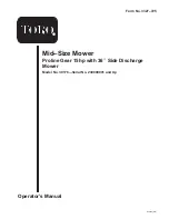
background image

Operator’s Manual

English (EN)

Form No. 3327–725

Mid–Size Mower

Proline Gear 15hp with 36

 Side Discharge

Mower

Model No. 30178—Serial No. 230000001 and Up

Summary of Contents for 30178

Page 1: ...Operator s Manual English EN Form No 3327 725 Mid Size Mower Proline Gear 15hp with 36 Side Discharge Mower Model No 30178 Serial No 230000001 and Up...

Page 2: ...alling the Traction Control Rods 14 Connecting the Throttle Cable 14 Installing the Blade Control PTO Rod 15 Installing the Shift Lever 15 Mounting the Fuel Tank 15 Operation 16 Page Think Safety Firs...

Page 3: ...ly with these safety instructions and always pay attention to the safety alert symbol which means CAUTION WARNING or DANGER personal safety instruction Failure to comply with the instruction may resul...

Page 4: ...ng the machine into or from a trailer or truck Use care when approaching blind corners shrubs trees or other objects that may obscure vision Maintenance and storage Disengage drives set parking brake...

Page 5: ...s or other attachments These can change the stability of the machine Keep all movement on slopes slow and gradual Do not make sudden changes in speed or direction Avoid starting or stopping on a slope...

Page 6: ...6...

Page 7: ...7 Slope Chart...

Page 8: ...8...

Page 9: ...s Safety decals and instructions are easily visible to the operator and are located near any area of potential danger Replace any decal that is damaged or lost 82 2280 82 2290 66 1340 67 5360 63 8440...

Page 10: ...erating the cutting blade 2 Push forward to engage 3 Pull back to disengage 98 0776 98 4387 1 Warning wear hearing protection 98 5130 1 Warning read the Operator s Manual for instructions on torquing...

Page 11: ...refuel such equipment on a truck or trailer from a portable container rather than from a gasoline dispenser nozzle If a gasoline dispenser nozzle must be used keep the nozzle in contact with the rim o...

Page 12: ...Installing the upper handle and wire harness Rod fitting Clevis pin Washer 1 4 in Hairpin cotter 2 2 2 4 Installing the traction control rods PTO rod Hairpin cotter 1 2 Installing the PTO rod Shift l...

Page 13: ...each side with 2 bolts 3 8 x 1 in and 2 locknuts 3 8 in Fig 3 3 Torque bolts to 25 ft lbs 34 N m m 4213 1 2 3 4 6 5 4 Figure 3 1 Upper handle 2 Rear frame 3 Bolt 3 8 x 1 in 4 Locknut 3 8 in 5 Low 6 H...

Page 14: ...on If adjustment is required remove hairpin cotter securing rod to upper control bar Thread rod in or out of trunion for proper position and install into upper control bar with hairpin cotter 5 After...

Page 15: ...ng washer and locknut Fig 10 3 Replace the spring washer dish down and locknut Fig 8 4 Torque nut to 35 ft lbs 47 N m 5 Shift lever to second gear and check alignment of lever in slot of shifter plate...

Page 16: ...ne and operate the machine Throttle Control The throttle control has Choke Fast Slow and Stop positions Bail The bail in conjunction with the PTO switch allows the engine to be started with the PTO di...

Page 17: ...ake lock Starting and Stopping the Engine Starting the Engine 1 Make sure spark plug wire s are installed on spark plug s and fuel valve is open 2 Move the blade control to off the shift lever to neut...

Page 18: ...es over center Fig 17 1 3 m 4194 2 Figure 17 1 Upper control bar 2 Bail 3 Blade control PTO Disengaging the Mower Blades PTO 1 To disengage the blade s pull blade control lever rearward all the way Fi...

Page 19: ...ng Brake page 17 3 Slowly press on the upper control bar to move forward Fig 18 To go straight apply equal pressure to both ends of the upper control bar Fig 18 To turn release pressure on the upper c...

Page 20: ...use injury or death Never remove the grass deflector from the mower because the grass deflector routes material down toward the turf If the grass deflector is ever damaged replace it immediately Never...

Page 21: ...e adjustment bolts can be installed in the desired hole location Fig 22 A tapered punch can be used to help align the holes 5 Tighten all 4 bolts and lower the unit 6 Adjust control rods and brake lin...

Page 22: ...3 in 76 mm C 1 1 1 7 8 in 48 mm 2 1 8 in 55 mm 2 3 8 in 61 mm 2 5 8 in 67 mm 2 7 8 in 73 mm C 2 0 2 1 8 in 55 mm 2 3 8 in 61 mm 2 5 8 in 67 mm 2 7 8 in 73 mm 3 1 8 in 79 mm C 2 1 2 1 4 in 58 mm 2 1 2...

Page 23: ...eaner service1 50 Hours Belts check for wear cracks Mower Belt check tension Mower Belt Idler Pivots grease Tires check pressure 100 Hours Paper Air Cleaner replace1 Oil change1 Engine clean outside T...

Page 24: ...Cutting Edge 2 Curved Area 3 Wear slot Forming Checking for Bent Blades 1 Rotate the blades until the ends face forward and backward Fig 25 Measure from a level surface to the cutting edge of the blad...

Page 25: ...rocedure until the blade is balanced 1 2 m 1855 Figure 29 1 Blade 2 Balancer Installing the Blades 1 Place the blade onto the bolt over cone washer Select proper number of spacer s for height of cut a...

Page 26: ...Never clean the paper element with pressurized air or liquids such as solvent gas or kerosene Replace the paper element if it is damaged defective or cannot be cleaned thoroughly 1 m 5192 2 Figure 32...

Page 27: ...e to raise the level to the full mark Important Do not overfill the crankcase with oil because the engine may be damaged 1 2 3 Figure 33 1 Oil dipstick 2 Metal end 3 Filler tube Changing the Engine Oi...

Page 28: ...electrodes is correct before installing the spark plug Use a spark plug wrench for removing and installing the spark plug s and a gapping tool feeler gauge to check and adjust the air gap Install a ne...

Page 29: ...d up of grass dirt or other debris from the cylinder and cylinder head cooling fins air intake screen on flywheel end and carburetor governor levers and linkage This will help insure adequate cooling...

Page 30: ...brake and press upper control bar very lightly approximately 1 2 in 13 mm wheels should rotate freely 4 If both conditions are met no adjustment is required Adjusting the Brakes The brake lever is on...

Page 31: ...ne onto the fuel filter Slide the hose clamp close to the filter to secure the fuel line m 3778 1 3 2 Figure 43 1 Fuel shut off valve 2 Fuel filter 3 Clamp Servicing the Fuel Filter Service Interval S...

Page 32: ...new belt around engine and drive pulleys Fig 46 6 Slide idler pulley in engine frame to tension traction belt Fig 46 7 Install the mower belt Fig 49 8 Check the belt guides under the engine frame for...

Page 33: ...des are properly adjusted Adjusting the Mower Belt Tension Service Interval Specification Check belt tension after the first 8 and 25 hours of operation Check the belt tension every 50 hours Important...

Page 34: ...awn mower unless you install a cover plate a mulch plate or a grass chute and catcher Warning 1 Remove the locknut bolt spring and spacer holding deflector to the mounts Fig 52 2 Straighten deflector...

Page 35: ...long term storage more than 90 days add stabilizer conditioner additive to fuel in the tank A Run engine to distribute conditioned fuel through the fuel system 5 minutes B Stop engine allow to cool a...

Page 36: ...level in crankcase is low 3 Add oil to crankcase 4 Cooling fins and air passages under engine blower housing are plugged 4 Remove obstruction from cooling fins and air passages 5 Spark plug is pitted...

Page 37: ...blade s 3 Mower is not level 3 Level mower from side to side and front to rear 4 Underside of mower is dirty 4 Clean the underside of the mower 5 Tire pressure is incorrect 5 Adjust tire pressure 6 Bl...

Page 38: ...38...

Page 39: ...39...

Page 40: ...ered There is no other express warranty except for special emission system coverage on some products This express warranty does not cover the following Cost of regular maintenance service or parts suc...

Reviews: