background image

Form No. 3419-198 Rev B

4045 Directional Drill

Software Versions A–C

Model No. 23823/A/C/TE/W—Serial No. 315000001 and Up

Model No. 23825/A/C/TE/W—Serial No. 315000001 and Up

Software Guide

Read this information carefully to learn how to operate
and maintain your product properly and to avoid
injury and product damage. You are responsible for
operating the product properly and safely.

Whenever you need service, genuine Toro parts, or
additional information, contact an Authorized Service
Dealer or Toro Customer Service and have the model
and serial numbers of your product ready.

You may contact Toro directly at www.Toro.com
for product safety and operation training materials,
accessory information, help finding a dealer, or to
register your product.

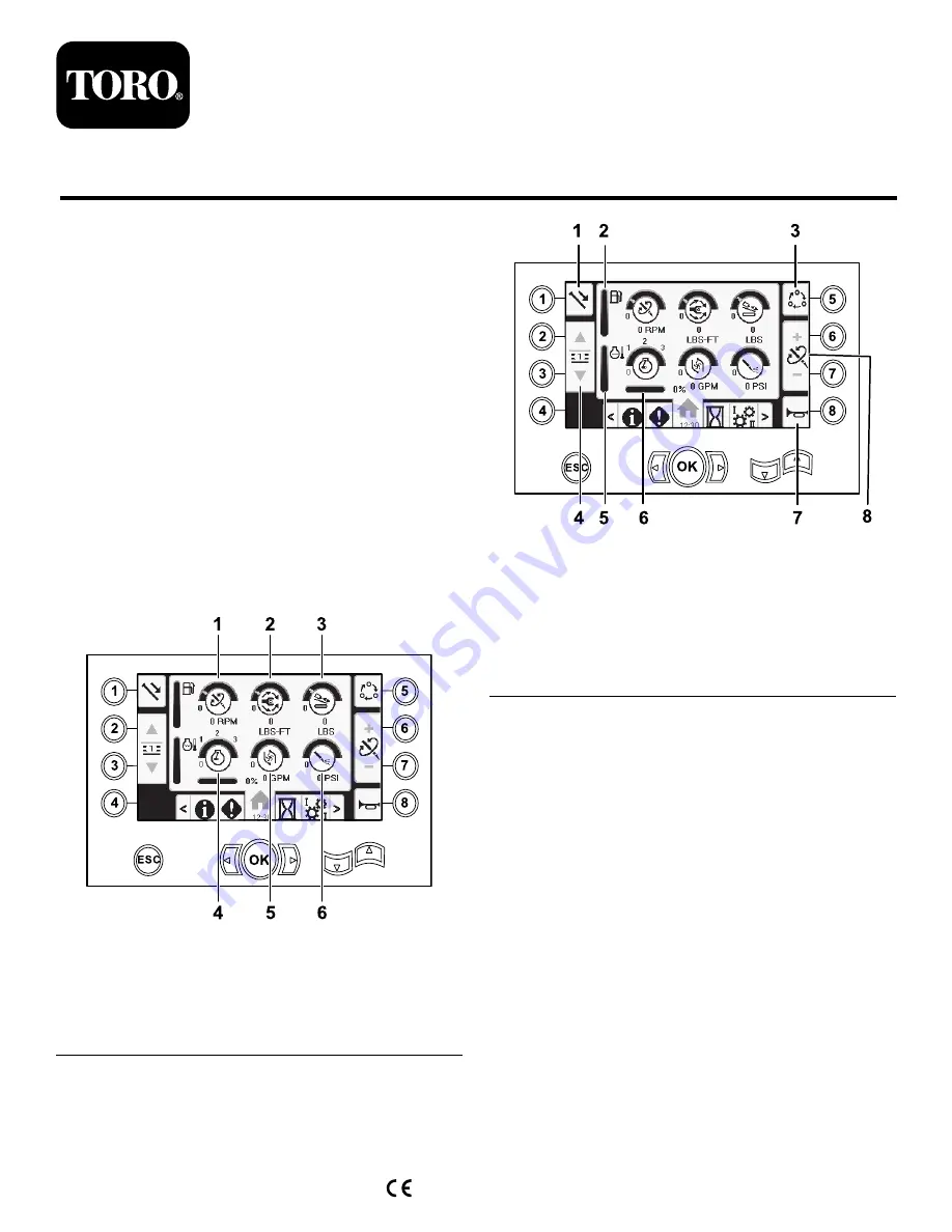
Main Information Screen

This is the first screen that appears after the initial
splash screen. To navigate between screens, use the
left and right arrows.

g214633

Figure 1

1.

Drill speed (rpm)

4.

Engine speed (rpm)

2.

Rotary torque

5.

Drilling-fluid flow rate

3.

Thrust force

6.

Drilling-fluid / Air-hammer
pressure

g214634

Figure 2

1.

Pipe functions

5.

Engine temperature gauge

2.

Fuel gauge

6.

Engine droop

3.

Limit setting options

7.

Horn

4.

Select pipe row

8.

Thrust force, drill speed
(rpm), or rotary torque
adjustment

Go to the

Mud or Air Hammer Selection Screen (page

12)

to switch between mud pressure and air hammer

functions.

Push button 1 to switch between the pipe functions
pull pipe, push pipe, and neutral.

Push button 5 to switch between thrust force, drill
speed (rpm), and rotary torque limits.

Use the up and down arrows to set the limits for
maximum drill speed (rpm), rotary torque, and thrust
force.

Thrust force: Change the thrust force limit by
pushing 6 or 7.

Drill speed (rpm): Change the drill speed rpm limit
by pushing 6 or 7.

Rotary torque: Change the rotary torque limit force
by pushing 6 or 7.

© 2019—The Toro® Company
8111 Lyndale Avenue South
Bloomington, MN 55420

Register at www.Toro.com.

Original Instructions (EN)

Printed in the USA

All Rights Reserved

*3419-198* B


Summary of Contents for 23823/A

Page 1: ...s g214633 Figure 1 1 Drill speed rpm 4 Engine speed rpm 2 Rotary torque 5 Drilling fluid flow rate 3 Thrust force 6 Drilling fluid Air hammer pressure g214634 Figure 2 1 Pipe functions 5 Engine temperature gauge 2 Fuel gauge 6 Engine droop 3 Limit setting options 7 Horn 4 Select pipe row 8 Thrust force drill speed rpm or rotary torque adjustment Go to the Mud or Air Hammer Selection Screen page 12...

Page 2: ...neutral manual mode to switch between Push Pull refer to Carriage Settings Screen page 10 to turn SmartTouch mode off The SmartTouch screens appears along the bottom of the home screen as shown below g231722 Figure 4 Pulling Pipe in SmartTouch Mode Start the SmartTouch mode with the cam assembly in the home position row 4 of the pipe box Important Ensure that you hold the lower section of the cam ...

Page 3: ... Pull pipe 2 Select pipe row 3 Hold the lower section of the rocker switch Figure 9 until the following 3 things happen Figure 10 A The cam assembly rotates toward the operator station B The elevator lowers C The loader arms rotate to the drill pipe g231712 Figure 8 g210462 Figure 9 g232376 Figure 10 3 ...

Page 4: ...Hold the upper button on the joystick to grip the pipe Figure 12 and Figure 13 and release the button g210533 Figure 12 g232377 Figure 13 7 Hold the lower section of the rocker switch Figure 15 until the arms rotate with the pipe back to the home position and the grippers open as the pipe enters the cam assembly pocket Figure 16 g231714 Figure 14 g210462 Figure 15 g232378 Figure 16 4 ...

Page 5: ...ipe box Figure 19 g210462 Figure 18 g232379 Figure 19 10 Release the rocker switch to proceed to the next step in the sequence Figure 20 g231716 Figure 20 11 Hold the lower section of the rocker switch Figure 21 until the elevator puts the pipe back in the pipe box and the cam rotates to the home position Figure 22 g210462 Figure 21 g232380 Figure 22 12 Release the rocker switch to start the pull ...

Page 6: ... switch on the left joystick completely down until all actions are complete to go to the previous step in the sequence Figure 24 g210061 Figure 24 1 Push button 1 to select push pipe Figure 25 2 Push buttons 2 and 3 to select the row where you want to get the pipe Figure 25 g232387 Figure 25 1 Push pipe 2 Select pipe row 3 Hold the lower section of the rocker switch Figure 27 until the cam assembl...

Page 7: ...he remaining pipe into the pipe box Figure 31 g210462 Figure 30 g232383 Figure 31 6 Release the rocker switch to proceed to the next step in the sequence Figure 32 g231719 Figure 32 7 Hold the lower section of the rocker switch Figure 33 until the loader arms rotate toward the pipe box As they rotate past the cam assembly the pipe grippers close on the pipe bringing it to the drill string Figure 3...

Page 8: ...e pipe Figure 37 and release the button g210527 Figure 36 g232385 Figure 37 11 Hold the lower section of the rocker switch Figure 39 until the loader arms rotate back and the cam assembly returns to the home position row 4 Figure 40 g231721 Figure 38 g210462 Figure 39 g232386 Figure 40 12 Release the rocker switch to start the push pipe process again The cam assembly goes to the row picked in step...

Page 9: ... reset the daily mud using button 8 g034784 Figure 42 Lubrication and Maintenance Screens To access this screen push button 3 on the Hours screen These screens provide the user with the daily maintenance schedules in the increments listed below To reset the maintenance interval navigate to the Parameters Options Screen page 11 push the down arrow to scroll to the maintenance options screen and ent...

Page 10: ...212 Figure 48 Control Mode Screen Push button 2 on the Settings screen Use this screen to select between the 2 joystick control options Push the up and down arrows to to switch between Mode I and Mode II g224024 Figure 49 Mode I The right joystick controls the thrust and the rotation functions The left joystick controls the wrench and pipe loader functions Mode II The right joystick controls the t...

Page 11: ...tween English units and metric units g224026 Figure 51 Screen Settings Push button 6 on the Settings screen to switch between zoom delay brightness and day or night mode Use the up and down arrows to adjust the parameters The Main Drilling Screen zooms into the drilling functions These settings adjust the delay on how long it takes to zoom g224028 Figure 52 Clock Settings Screen Push button 7 on t...

Page 12: ...on or break lower icon as the selected rotary joystick is moved The carriage indicates a voltage range from 0 0 to 10 0 V in the joystick selected direction for thrust or pullback The lower left icon indicates the carriage position of wrench load or carriage back as the carriage moves to the most rearward positions The lower center icon indicates if the 2 speed selection of the carriage speed has ...

Page 13: ...to maintain the lowest value Push the up and down arrows to select the droop value Cam Arm I O Screen To access this screen push button 3 on the I O screen Use this screen to adjust the cam and pipe loader calibration options g213146 Figure 57 1 Push button 3 to calibrate The 2 voltages on the bottom indicate the loader arm and cam actual voltage from the sensors The voltages range from 1 0 to 4 0...

Page 14: ...wn the indicator turns green with a blue down decrease arrow The icon is black when the rocker switch is not pressed Processor indicator icon shows a red X to indicate a problem with the expansion processor located next to the main controller Travel Pendant I O Screen To access this screen push button 7 on the I O screen The travel pendant screen shows the voltage and position of the joystick loca...

Page 15: ...software version g213171 Figure 63 Carriage Crash Warning Icon The carriage crash warning screen Figure 64 appears if the following occurs The carriage is in the drill area and you try to operate the loader arm or pipe cam or You try to operate the carriage when the loader arm or pipe cam is not in the home position g210794 Figure 64 To clear this warning do the following Move the cam assembly to ...

Page 16: ...Stake Down Cage Warning Icon CE models only This icon Figure 67 displays if the stake down cage door is not closed g223941 Figure 67 16 ...

Reviews: