TomTom LINK 3000, Installation Manual
The TomTom LINK 3000 is an innovative vehicle tracking device that revolutionizes fleet management. Ensure a seamless installation with the comprehensive Installation Manual available for free download from our website. This manual provides step-by-step instructions to effortlessly optimize your fleet's performance and maximize efficiency.
Share
Download


Reviews:
No comments
Related manuals for LINK 3000

GPSMAP 190-00557-00
Brand: Garmin Pages: 58

ST-901L
Brand: Sinotrack Pages: 24

S709
Brand: WhatsGPS Pages: 14

AmeriGo 16006D
Brand: Royal Pages: 2

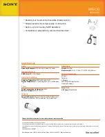
nav-u NV-U83
Brand: Sony Pages: 2
GPS-CS1 - Digital Camera GPS Unit
Brand: Sony Pages: 1
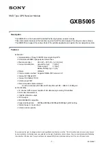
GXB5005
Brand: Sony Pages: 15
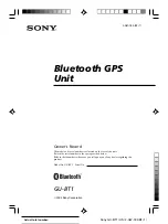
GU-BT1
Brand: Sony Pages: 16

NAV-U NVD-U11E
Brand: Sony Pages: 25

NAV-U NVD-U13E NAV-U NVD-U13R
Brand: Sony Pages: 51

NAV-U NV-U71T
Brand: Sony Pages: 56
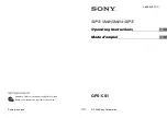
GPS-CS1 - Digital Camera GPS Unit
Brand: Sony Pages: 59

GPS-CS1KA
Brand: Sony Pages: 75

HKDW-704
Brand: Sony Pages: 144

nav-u NV-U50
Brand: Sony Pages: 216

GPS
Brand: Flymaster Pages: 58

Earthmate GPS PN-60
Brand: DeLorme Pages: 109

A Series
Brand: AOVX Pages: 14


